LGW-SH Gateway Web Configuration Guide
AdoModel Tech Inc. — Web configuration guide for the LGW915SH mini indoor LoRaWAN gateway.
1. Overview
1.1 Requirements and Purpose
This document is the web configuration guide for the LGW915SH mini indoor gateway.
1.2 Terms and Abbreviations
Table of Terms
| Term | Definition |
|---|
Table of Abbreviations
| Term | Definition |
|---|
1.3 References
<Omitted>
2. Mini Indoor Gateway Introduction
2.1 Appearance
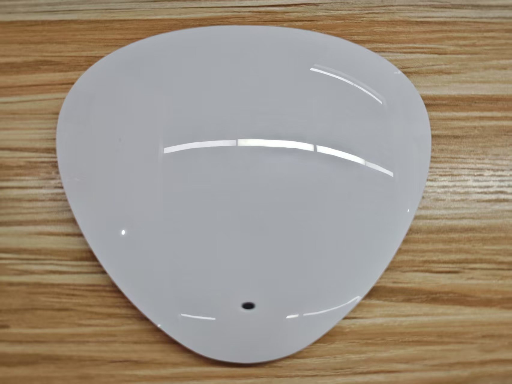
The gateway features a streamlined pebble-and-water-drop design with a glossy pure-white shell. Its rounded, smooth curves have no sharp edges, and the device is slim, light, and compact. The front of the device is an integrated smooth shell with a small status indicator opening at the top-left corner and no extra buttons, giving it a minimalist look that suits a wide range of small industrial and office environments. The rear of the device features an integrated recessed interface slot that neatly houses the power jack, network port, and buttons, so cables do not protrude after being plugged in, preserving the device's sleek profile.
The device supports two installation methods — flat placement on a desktop and wall mounting — making it suitable for weak-current boxes, walls, desktops, and other locations.
2.2 Interface Description
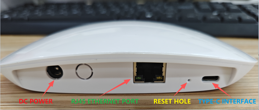
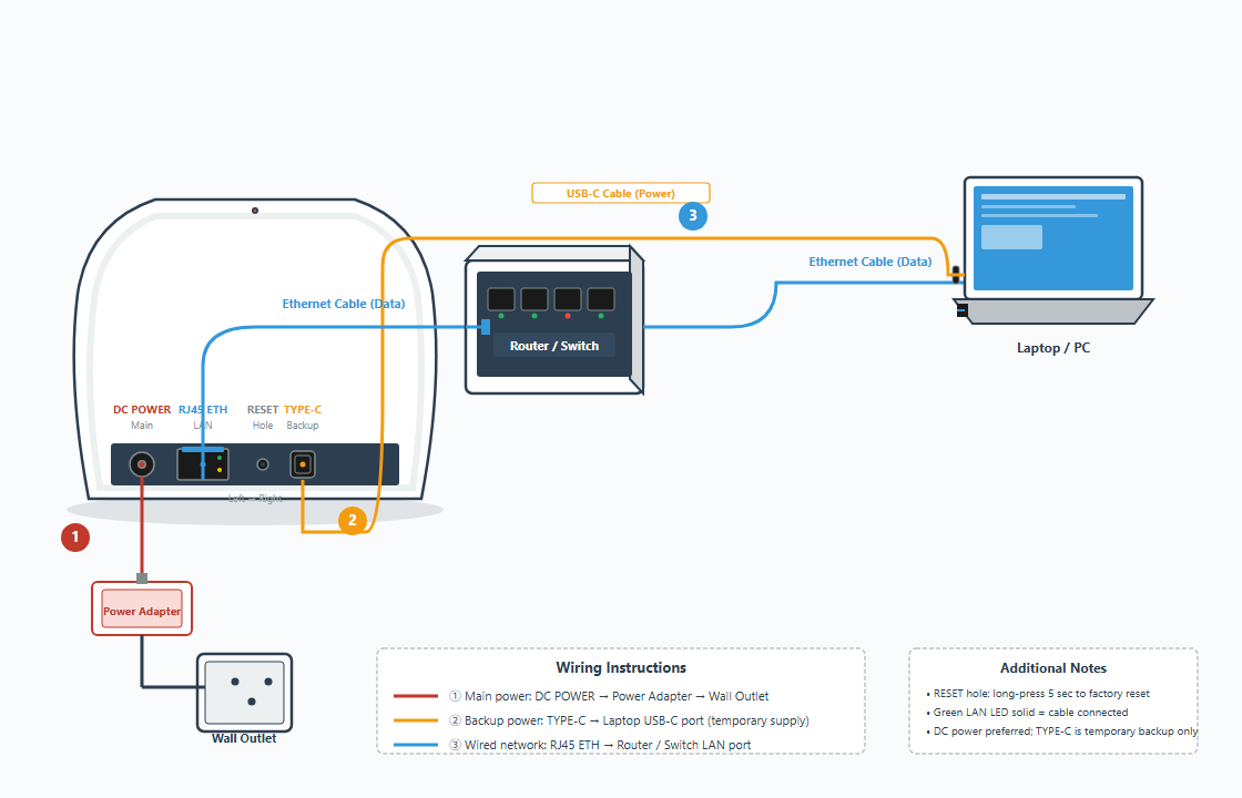
The interfaces on the rear of the device are arranged from left to right. The functions of each interface and button are described below:
| No. | Interface / Button | Description |
|---|---|---|
| (1) | DC Power Jack | The main power input of the device, matching the DC power adapter included in the package. Input specification: 12 V/2 A. It provides the primary power for stable device operation. |
| (2) | RJ45 Ethernet Port | A standard wired network interface that connects to a router or a switch via an Ethernet cable for LAN and cloud data transmission. The port has a built-in dual-color status LED: a solid green light indicates a normal physical cable connection, and a flashing yellow light indicates that the device is sending and receiving network data. |
| (3) | Reset Pinhole | The system reset button of the device. Press and hold it with a slender object such as a toothpick or a pin, and release after 5 seconds. The device will be restored to factory settings, and all network and device configurations will be cleared. |
| (4) | Type-C Port | It has dual functions: auxiliary power supply — a phone Type-C charging cable can be used to temporarily power the gateway; and a debug serial port — when connected to a computer, it allows reading device operation logs and debugging local device parameters. |
2.3 Status Indicator
The front of the device has a three-color status indicator (red / green / blue). Each color reports one aspect of the gateway's operation:
(1) Red — System Power and Basic Operation
| State | Meaning |
|---|---|
| Solid | The device is powered on and running normally. |
| Off | The device is not powered, or a power fault has occurred. |
| Blinking slowly | The system is booting up or a factory reset is in progress. |
| Blinking fast | The system has encountered a fault or critical error. |
(2) Green — IP Network Connection
| State | Meaning |
|---|---|
| Solid | An IP address has been obtained and the network connection is up. |
| Off | The network is not connected or not enabled. |
| Blinking | The gateway is trying to connect to the network (Wi-Fi / Ethernet searching or dialing). |
(3) Blue — LoRaWAN Service
| State | Meaning |
|---|---|
| Solid | The LoRaWAN Packet Forwarder is running normally and connected to the LoRaWAN network server. |
| Off | The LoRaWAN module is not started, or no network server is configured. |
| Blinking | LoRa packets are being received or sent (RF activity). |
3. Hardware Installation and Wiring
3.1 Power Supply Options
The device supports two power supply methods. The DC power adapter is the preferred method; Type-C is only for temporary backup power.
- Primary power: Plug the included power adapter into the DC jack on the rear of the device, and plug the adapter into a wall outlet.
- Backup power: Use a Type-C data cable, plug one end into the gateway's Type-C port and the other end into a charging adapter for temporary power.
3.2 Wired Network Connection
Prepare a standard Cat5e/Cat6 Ethernet cable. Plug one end into the RJ45 port on the rear of the gateway and the other end into a router LAN port or a switch port. A solid green light on the port indicates a successful cable connection.
4. Basic Device Network Configuration
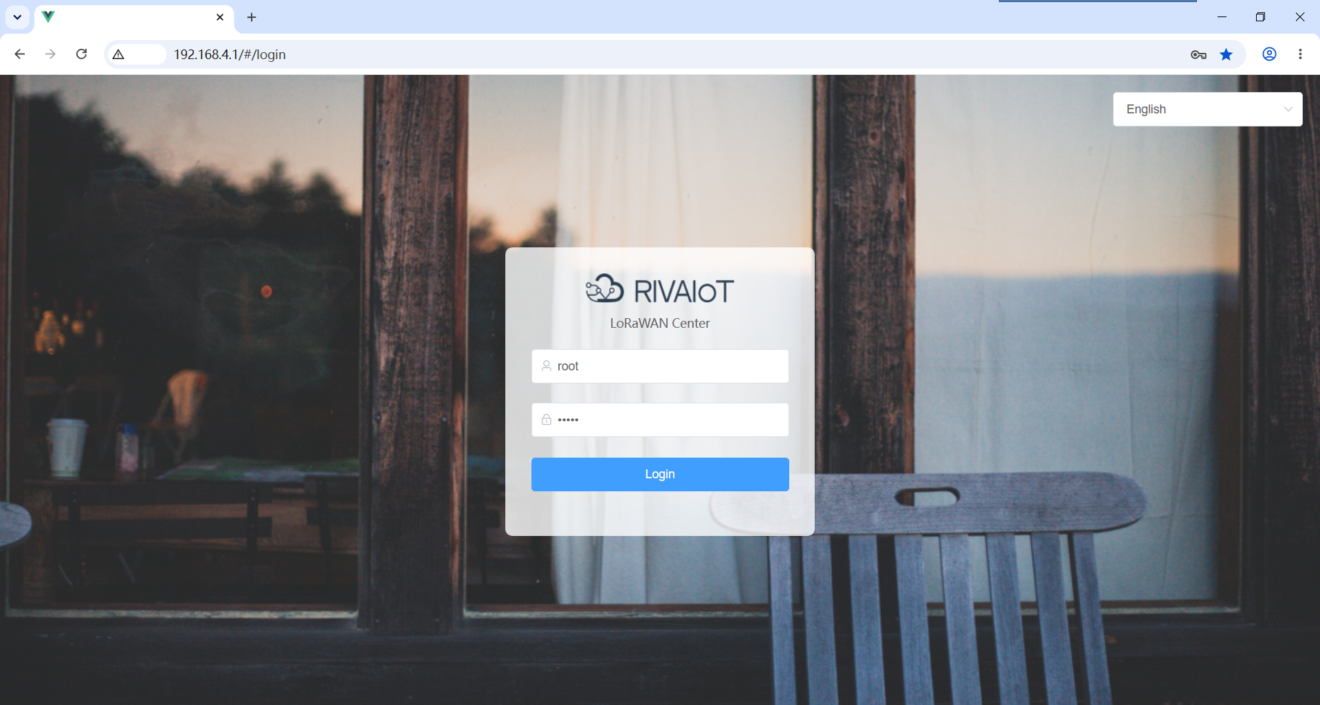
4.1 Logging In to the Web Management Interface
- On your computer, find the Wi-Fi hotspot and connect to the Wi-Fi network
LGW_XXXX..., then enter the hotspot password:lgwwifipsw. - Open a browser and visit
http://192.168.4.1, enter the usernamerootand the passwordadmin, and log in to the management interface.
5. Home Page: Viewing the Gateway Operation Overview
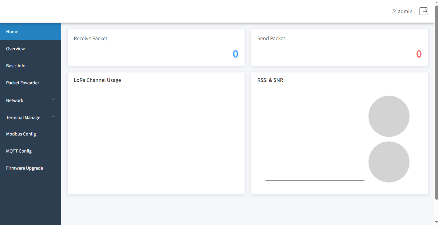
After logging in, you can view the gateway operation overview on the Home page, mainly including:
- Number of uplink messages: the number of uplink messages received by the gateway from terminals.
- Number of downlink messages: the number of downlink messages sent by the gateway to terminals.
- LoRa channel usage: displays the usage of each channel in chart form.
- RSSI and SNR information: used to understand the wireless communication quality.
The Home page data is used for operation monitoring and preliminary fault diagnosis. If there are no uplink messages for a long time, check in sequence whether the terminal is working properly, whether the gateway RF configuration is correct, and whether the network connection is normal.
6. Overview: Viewing Device Information
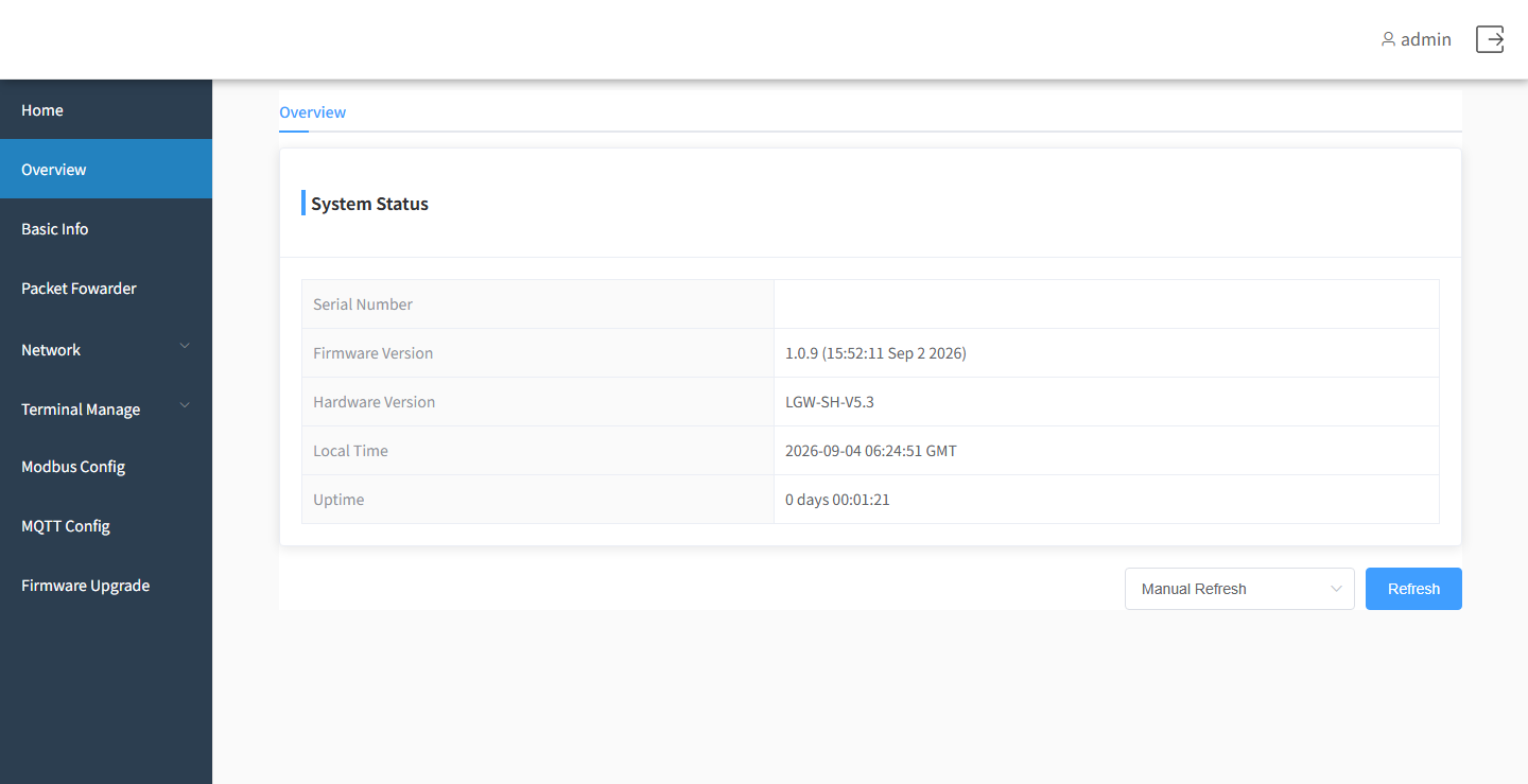
On the Overview page, you can view the current operating status of the device, including:
- Device serial number;
- Firmware version;
- Hardware version;
- Device local time;
- Device uptime.
Click Refresh to re-read the device status. If the device time, uptime, or version information is abnormal, refresh the page to confirm first. If the issue persists, contact device maintenance personnel.
7. Basic Information and Device Management
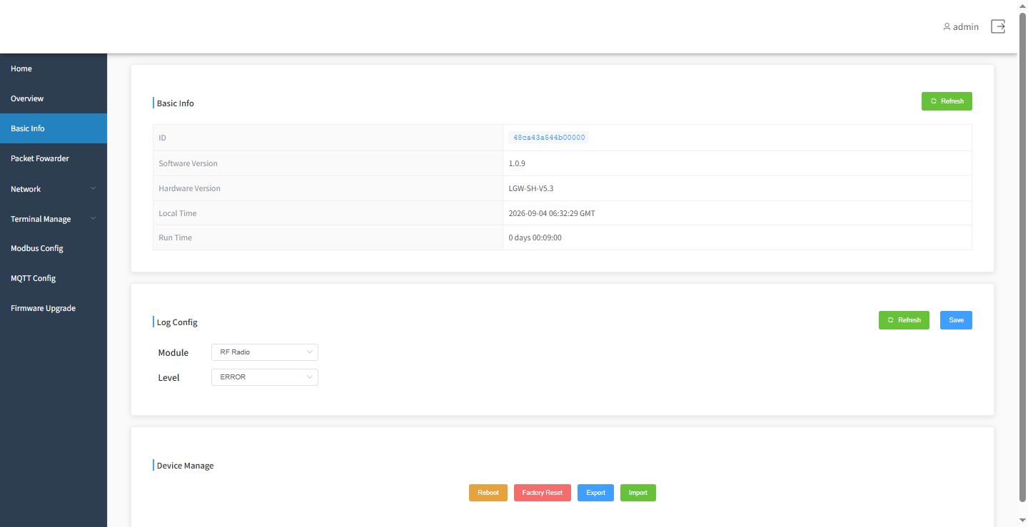
On the Basic Information page, you can view device information, configure logs, and perform device management operations.
7.1 Viewing Basic Information
The page displays the device ID, software version, hardware version, local time, and uptime. Click the Refresh button to obtain the latest information.
7.2 Log Settings
Log settings are used to adjust the logging level of device operation logs and remote log parameters.
- Module: select the function module to be configured.
- Level (log level): select ERROR, WARN, INFO, DEBUG, or Verbose.
| Level | Description |
|---|---|
| ERROR | Records error information only. |
| WARN | Records warning and error information. |
| INFO | Records general operation information, warnings, and errors. |
| DEBUG | Records detailed debugging information. |
| Verbose | Records the most detailed information. |
- Remote log server: enter the address of the server that receives the logs.
- Remote log port: enter the port number used by the remote log server.
After modification, click Save to apply the settings.
7.3 Device Management
7.3.1 Restarting the Device
Click Restart and confirm; the device will restart. During the restart, the Web page may be temporarily inaccessible. Please wait for the device to start up completely, then log in again.
7.3.2 Restoring Factory Settings
Click Restore Factory Settings and confirm; the device will be restored to its default configuration. This operation may clear network, gateway, terminal, and other service configurations. Before performing this operation, make sure the configuration has been backed up.
7.3.3 Exporting Configuration
Click Export Configuration to save the current device configuration to your computer. It is recommended to save a configuration file after the initial configuration, before major changes, and before upgrades.
7.3.4 Importing Configuration
Click Import Configuration, select the previously exported JSON configuration file, and upload it. Before importing, make sure the configuration file comes from a device of the same or a compatible model. After the import, some configurations may require a device restart to take full effect.
8. Gateway Configuration
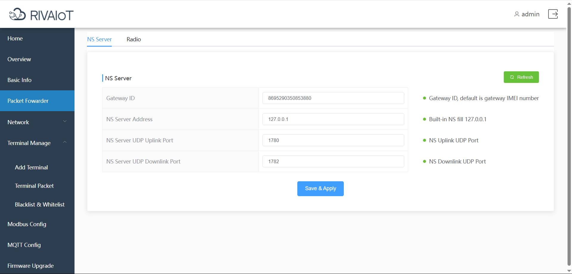
8.1 NS Network Server Settings
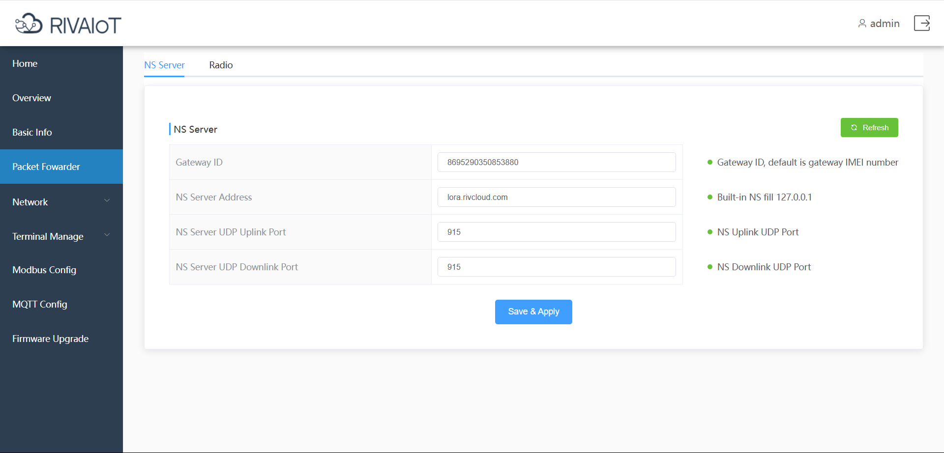
On the network server configuration page, fill in:
- Gateway ID: the unique identifier of the gateway on the network server.
- Server address: the IP address or domain name of the network server. For the built-in NS, enter
127.0.0.1orlocalhost; for an external NS, enter the actual address, e.g.,adomodelcloud.com. - Uplink port: the port used by the gateway to send uplink data to the network server. For the built-in NS, enter
1780; for an external NS, enter the actual port, e.g.,915. - Downlink port: the port used by the gateway to receive downlink data from the network server. For the built-in NS, enter
1782; for an external NS, enter the actual port, e.g.,915.
After confirming that the server address and ports are correct, click Save. If the gateway cannot connect to the network server, check the server address, ports, firewall, and the gateway's network connection.
8.2 RF Settings
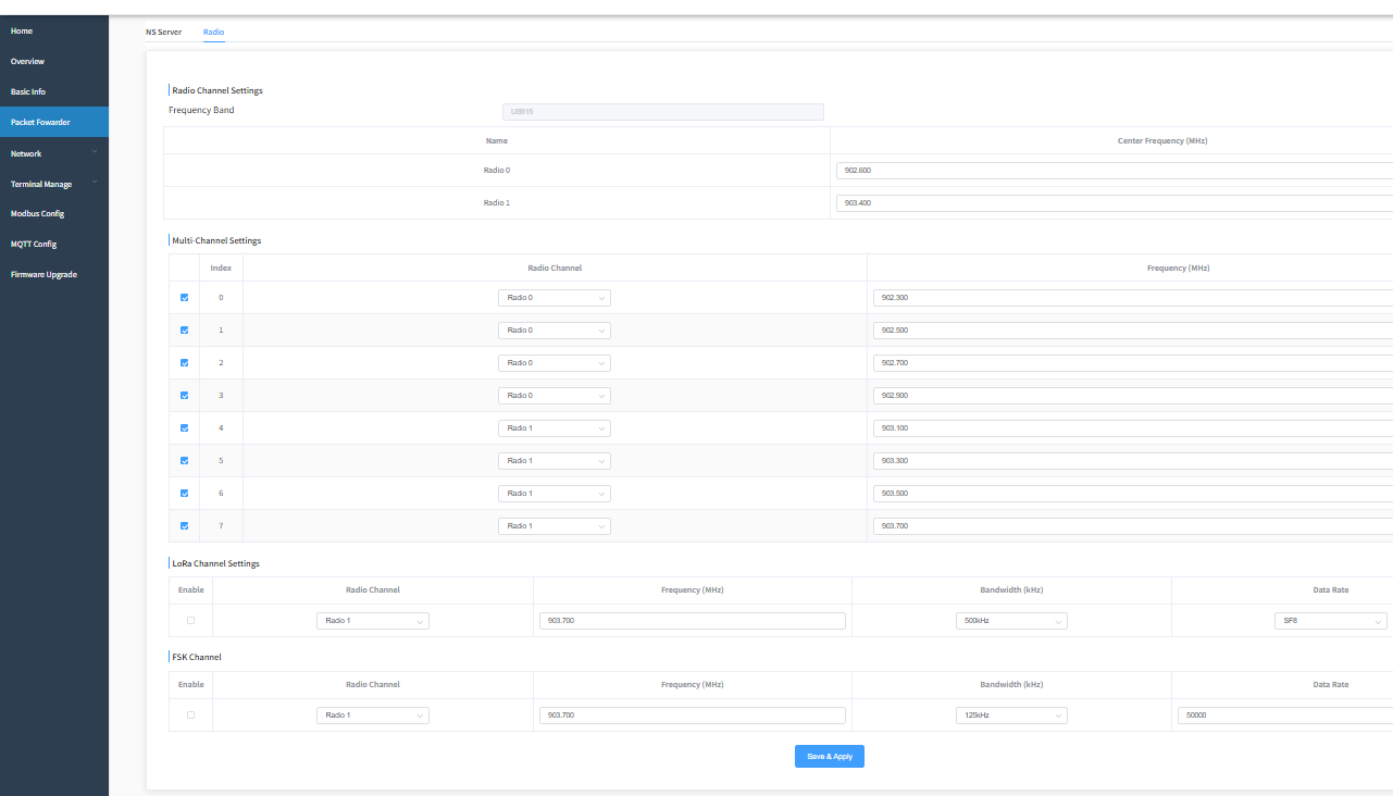
RF settings determine the frequency and channels used by the gateway when receiving signals from LoRa terminals.
- Band: displays the frequency band supported by the device; it is usually not directly modifiable.
- RF channel: displays the RF channels and their center frequencies.
- LoRa channel: view or set the enable status, frequency, bandwidth, and data rate.
- FSK channel: view or set the enable status and frequency parameters of the FSK channels.
After modification, click Save. If you are unsure about the parameter values, use the device default configuration or contact technical support.
9. Network Settings
9.1 Ethernet Settings
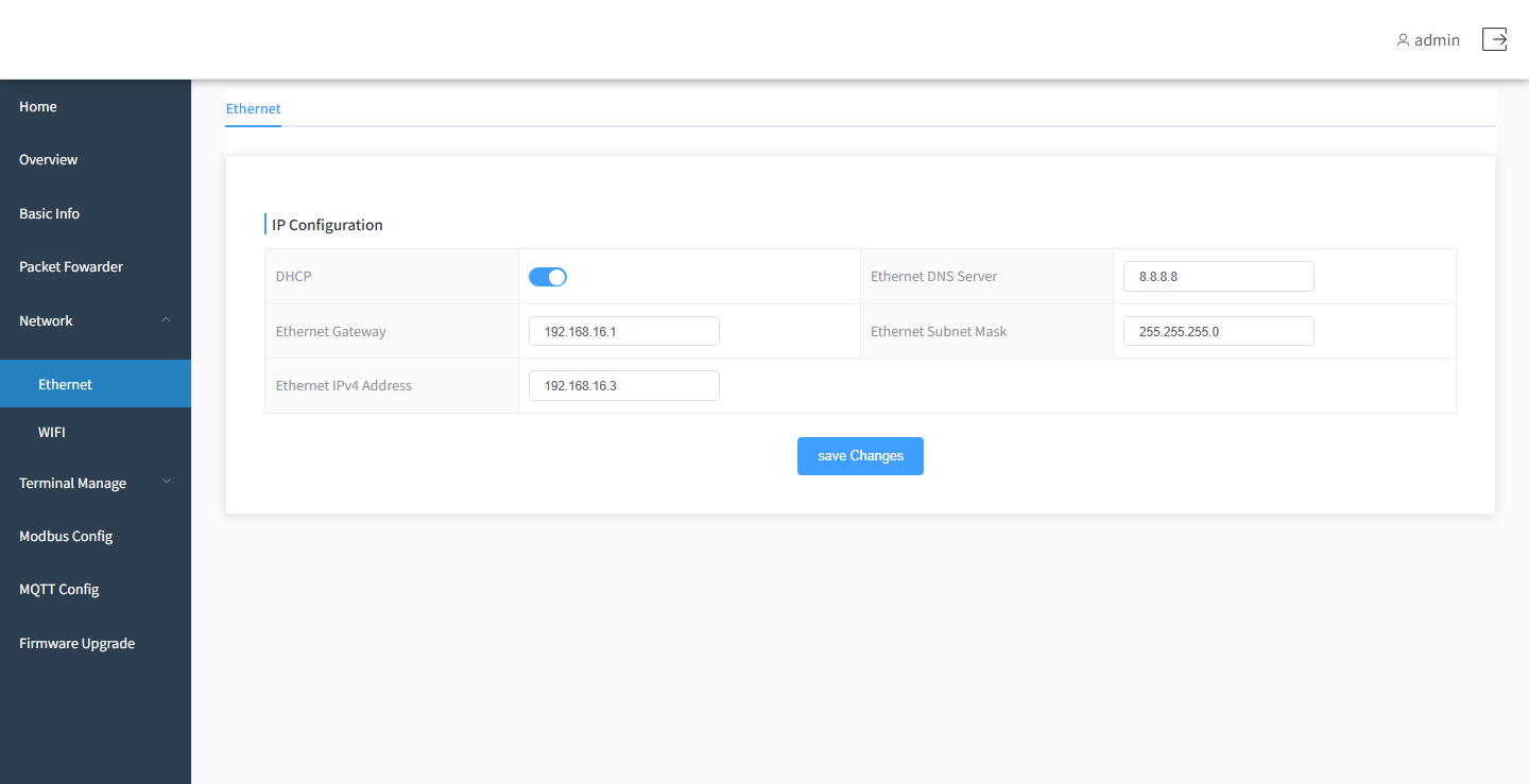
Go to Network > Ethernet to configure the port parameters.
9.1.1 DHCP (Automatic IP Acquisition)
When DHCP is enabled, the gateway automatically obtains the IP address, subnet mask, gateway, and DNS from the DHCP server on the network. This applies to scenarios where DHCP service is already deployed on the network.
9.1.2 Manual Network Parameter Settings
When DHCP is disabled, you need to fill in the following manually:
- IP address: the fixed address of the gateway on the LAN.
- Subnet mask: the subnet mask of the current network.
- Gateway: the address of the network egress device.
- DNS: the domain name resolution server address.
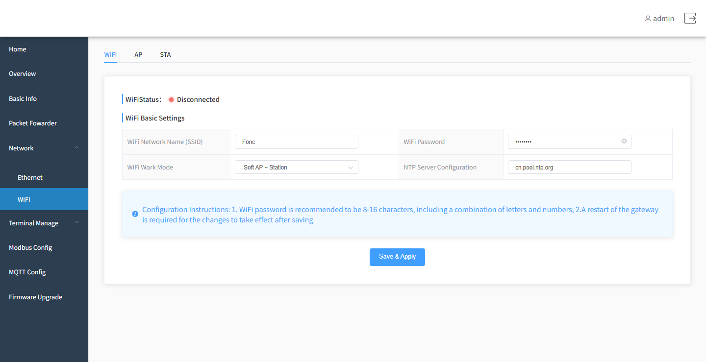
9.2 WiFi Settings
Go to Network > WiFi to configure the WiFi working mode and AP/STA network parameters.
9.2.1 WiFi Basic Settings
- SSID: the name of the wireless network to connect to.
- Password: the password of the wireless network.
- Working mode:
- Soft AP: the gateway acts as a wireless hotspot for other devices to connect to.
- Station: the gateway connects to an existing wireless network.
- Soft AP + Station: provides a hotspot and connects to an existing wireless network at the same time.
- NTP server: the address of the time server used to calibrate the device time.
After filling in or modifying, click Save.
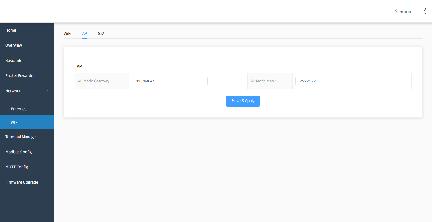
9.2.2 AP Settings
AP settings are used to configure the network parameters used when the gateway acts as a wireless hotspot:
- AP gateway: the gateway address of the hotspot network.
- AP subnet mask: the subnet mask of the hotspot network.
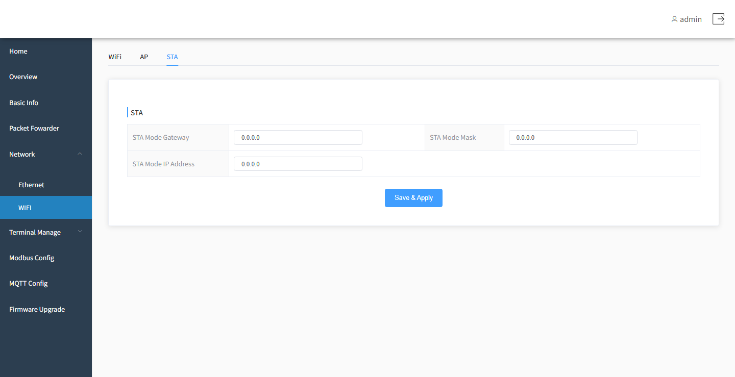
9.2.3 STA Settings
STA settings are used to configure the network parameters used when the gateway connects to an external wireless network:
- STA gateway: the gateway address of the external wireless network.
- STA subnet mask: the subnet mask of the external wireless network.
- STA IP: the IP address of the gateway on the external wireless network.
The page displays the current WiFi connection status, including Connecting, Connected, or Disconnected. After saving the WiFi configuration, wait for the status to be re-established. If the status remains disconnected, check the SSID, password, signal strength, and network address settings.
10. Terminal Management
10.1 Adding Terminal Devices
Go to Terminal Management > Add Terminal to add, view, and delete LoRa terminal devices.
10.1.1 Network Join Methods
LoRa terminals support two network join methods. Switch to the method actually used on the page:
- OTAA: the terminal requests to join the network through its DevEUI and AppKey. This method is more secure and is recommended.
- ABP: the terminal joins the network directly with a fixed network address and session keys, without a join procedure.
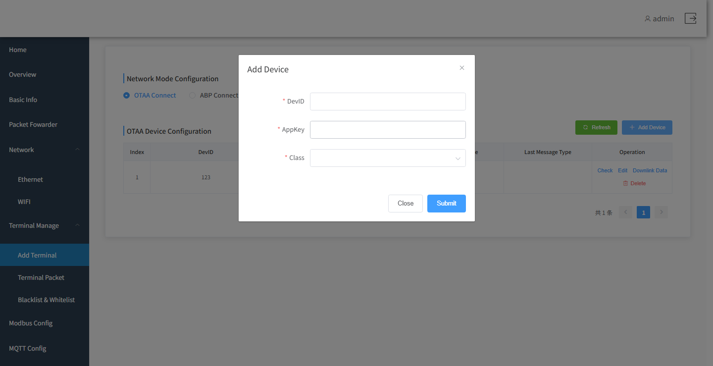
10.1.2 OTAA Join Parameters
- DevEUI: the unique identifier of the terminal device (64-bit hexadecimal).
- AppKey: the application key, provided by the network server.
- Class: the working mode of the terminal; select Class A or Class C.
10.1.3 ABP Join Parameters
For ABP, in addition to DevEUI and Class, you also need to fill in:
- DevAddr: the short address of the terminal in the system.
- AppSKey: the application session key.
- NwkSKey: the network session key.
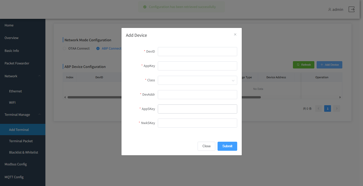
10.1.4 Procedure
- Select the join method (OTAA or ABP).
- Click Add, and fill in the above parameters in the pop-up window.
- Click OK to save the device.
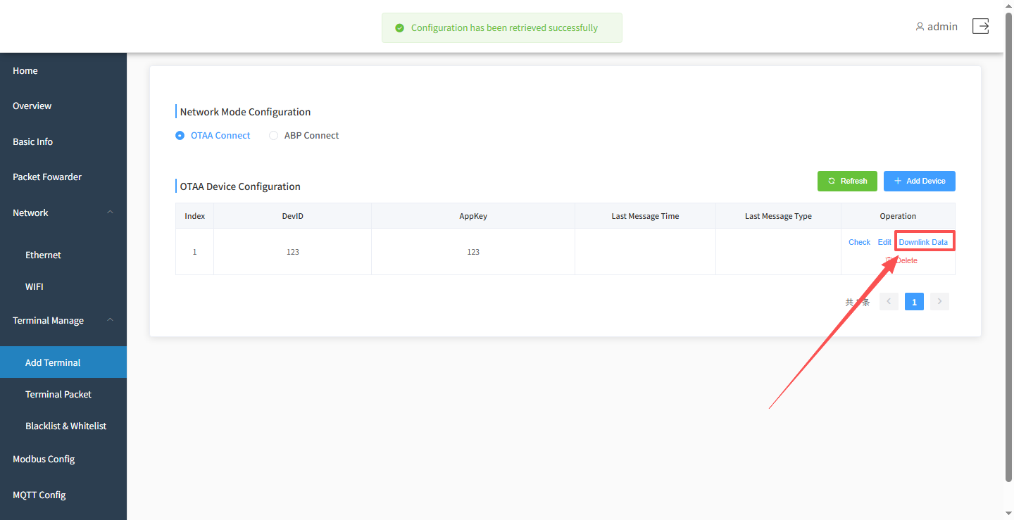
- The device list displays the DevEUI, keys, last message time, and last message type of each terminal.
To modify a device, click Edit in the list; to remove a device no longer in use, click Delete to remove it from the gateway.
10.2 Downlink Data
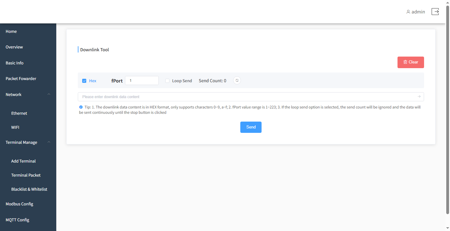
Go to the Downlink Data page (usually entered via the Send Data operation on the Add Terminal page) to send downlink commands to a specified terminal.
10.2.1 Parameter Description
- deveui: the target terminal, automatically carried over from the previous page.
- Hex mode: when enabled, the data is parsed in hexadecimal.
- fPort: the LoRa port number, ranging from 1 to 255; it must be consistent with the agreement on the terminal side.
- Data: the message content to be sent to the terminal.
- Cyclic sending: when enabled, sends repeatedly every 1 second.
- Send count: counts the number of messages sent.
After entering the data, press Enter or click the Send button to send it. When cyclic sending is enabled, the page keeps sending and updating the count, and stops automatically when you leave the page.
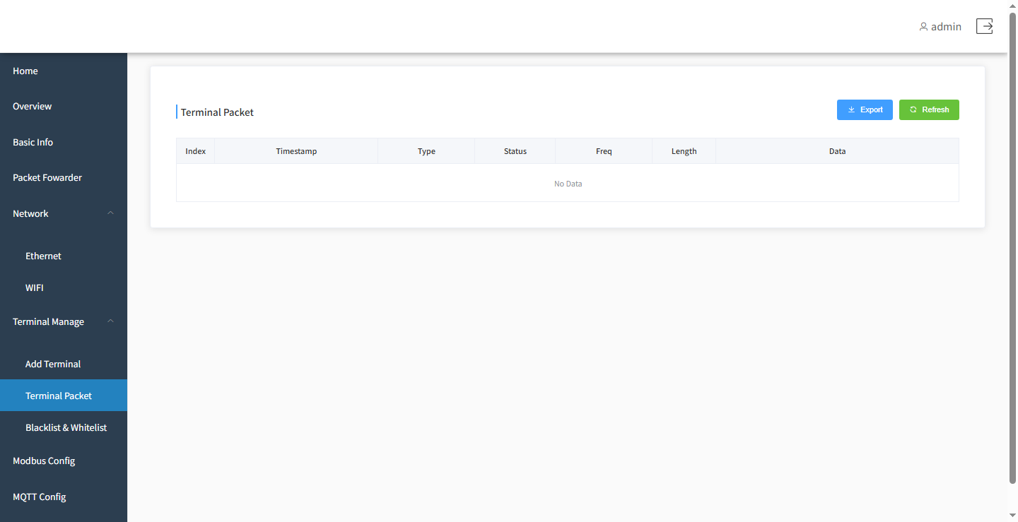
10.3 Viewing Terminal Messages
Go to Terminal Management > Terminal Messages to view the uplink/downlink message records of terminals, including:
- Timestamp;
- Message type;
- Message status;
- Frequency point;
- Data length;
- Data content (when the data is long, hover the mouse over the data column to view the full content).
The page supports refreshing to obtain the latest messages. You can also click Export to save the message records locally for analysis or archiving.
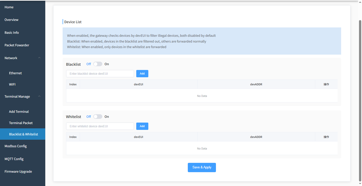
10.4 Blacklist/Whitelist
Go to Terminal Management > Blacklist/Whitelist to control which terminals can communicate with the gateway. The blacklist/whitelist is disabled by default.
10.4.1 Blacklist
After the blacklist is enabled, terminals on the blacklist are filtered out, while other terminals communicate normally.
Enter the devEUI of the terminal to be filtered and click Add to add it to the blacklist. To lift the filtering, delete the corresponding entry from the list.
10.4.2 Whitelist
After the whitelist is enabled, only terminals on the whitelist can communicate with the gateway; all other terminals are not forwarded.
Enter the devEUI of the terminal allowed to communicate and click Add to add it to the whitelist. To restore communication, delete the corresponding entry from the list.
11. Modbus Configuration
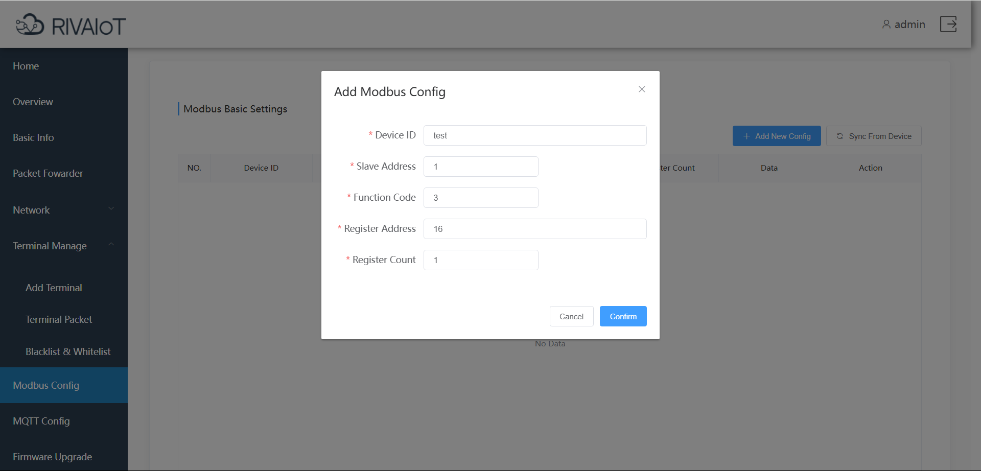
Go to the Modbus page to configure the cached data rules between the gateway and Modbus slave devices. The list displays the device ID, slave address, function code, register address, register count, data, and other information.
11.1 RS485-to-Ethernet Using USR-DR134
11.1.1 Viewing the Gateway Configuration
Use the built-in NS with address 127.0.0.1 or localhost, uplink port 1780, and downlink port 1782, then click Save.
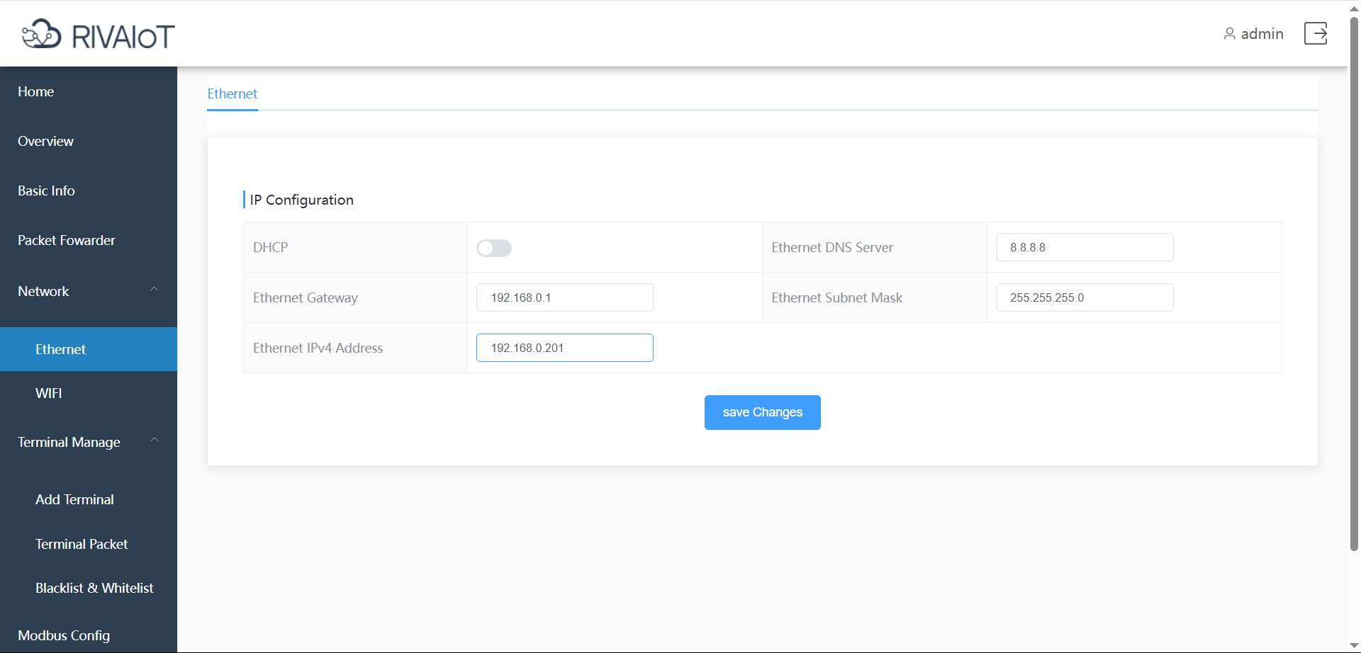
11.1.2 Network Ethernet Configuration
- Gateway address:
192.168.0.1 - Device address:
192.168.0.201 - Mask:
255.255.255.0 - Disable DHCP
- Save
11.1.3 Configuring Modbus
Fill in according to the actual register addresses.
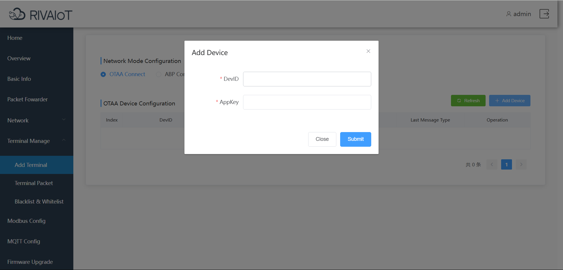
11.1.4 OTAA Device Join Configuration
Enter the ID and key of the DTU device to be joined, then submit.
11.1.5 Hardware Connection
The hardware wiring is as follows:

11.1.6 Using open modscan
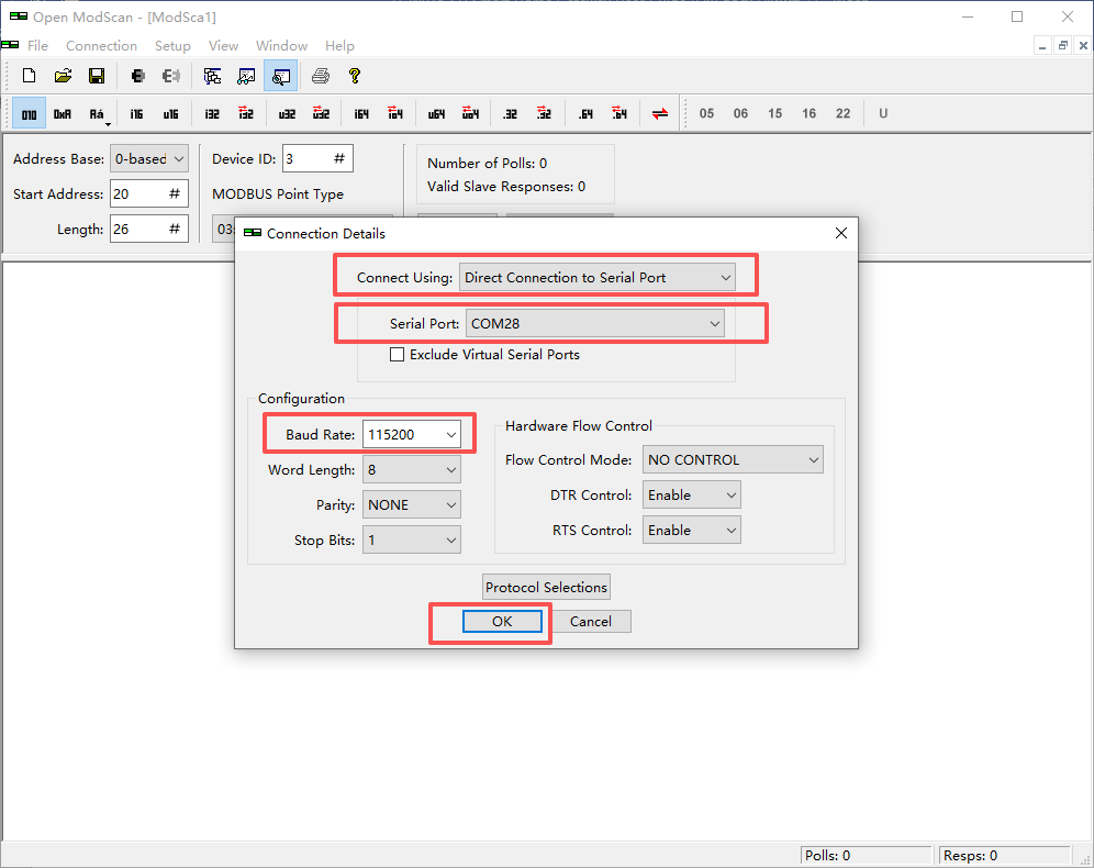
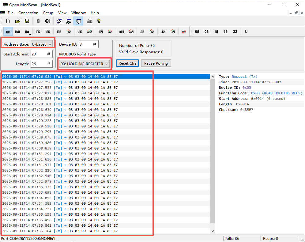
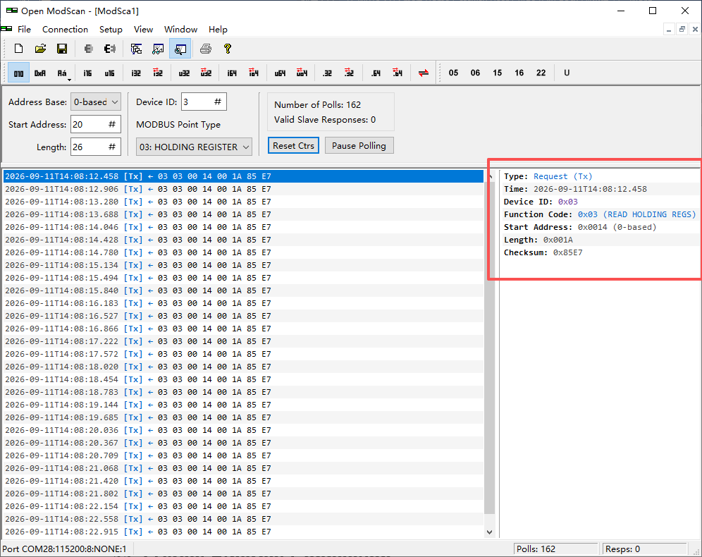
Open open modscan, select the serial port, connect, configure the Modbus register addresses, and start polling and collecting data.
11.2 Direct Ethernet Connection
11.2.1 Querying the Gateway IP
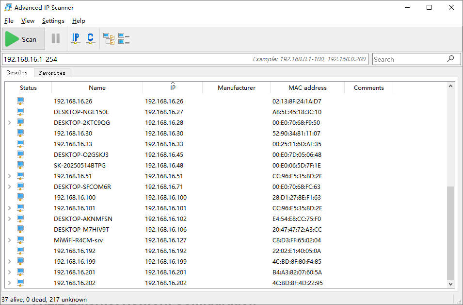
The supplied LoraGW_IPScan tool can be used to detect the IP address of the gateway device, monitor its online/offline status, and check the gateway by plugging and unplugging the network cable. LoraGW_IPScan can be downloaded from www.adomodeltech.com or obtained from your account manager.
11.2.2 Ethernet Network Configuration
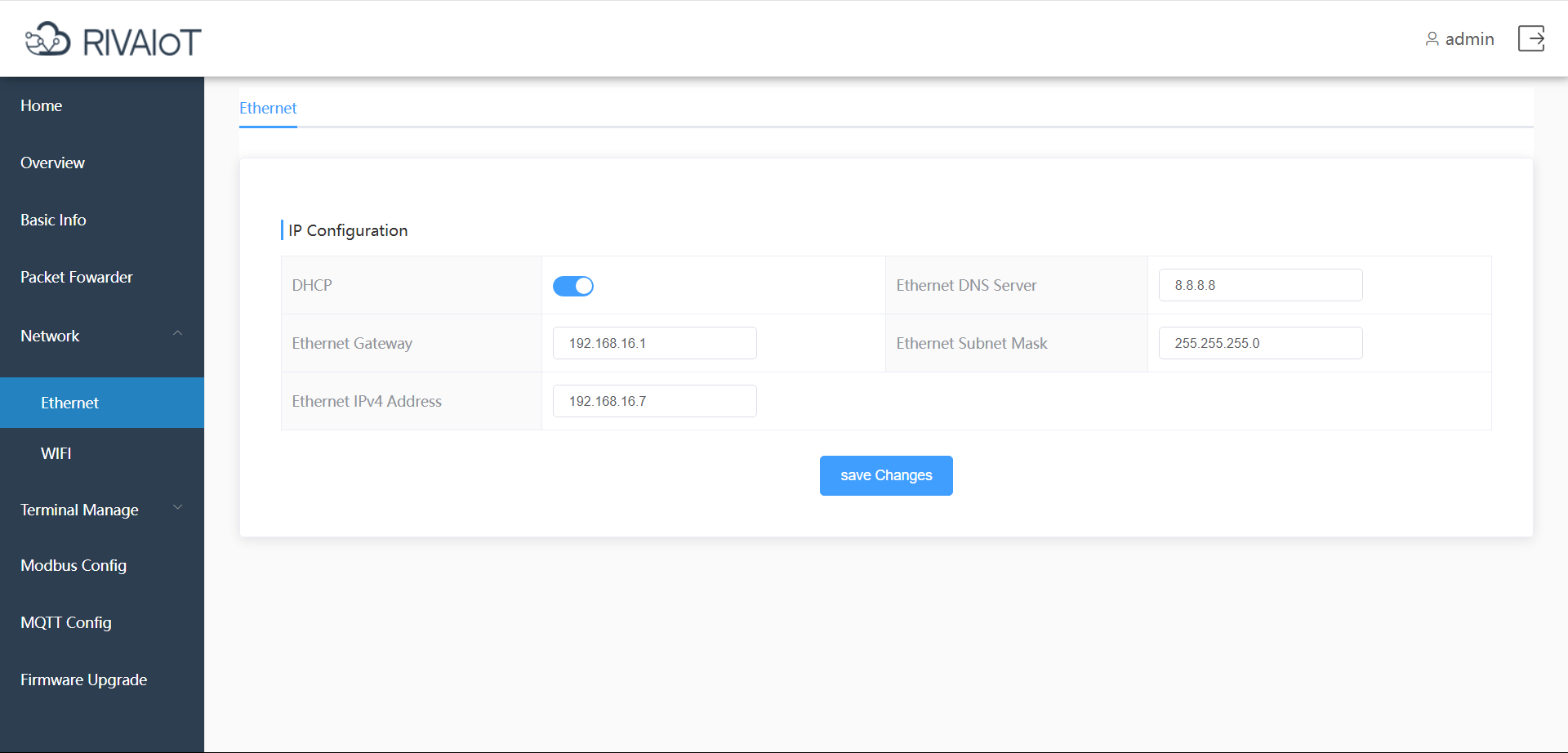
For a direct Ethernet connection, DHCP can be enabled. The remaining configuration operations are shown in the figure below.
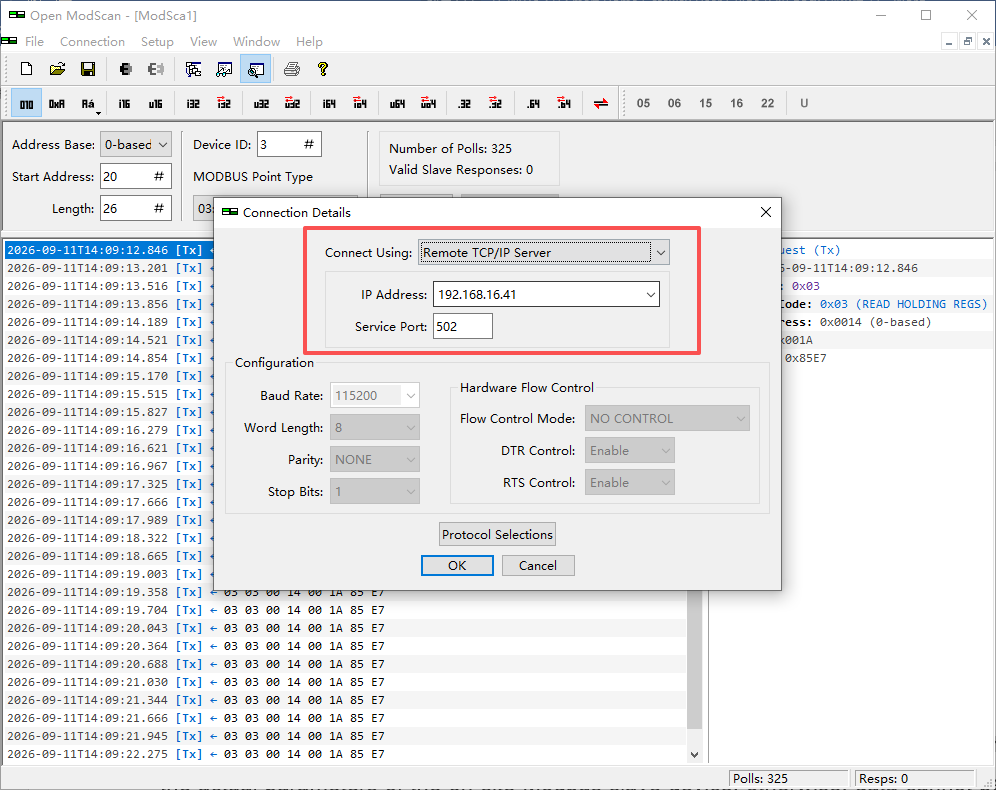
The connection is as follows:

Use open modscan; when starting polling in open modscan, select IP to connect.
12. MQTT Configuration
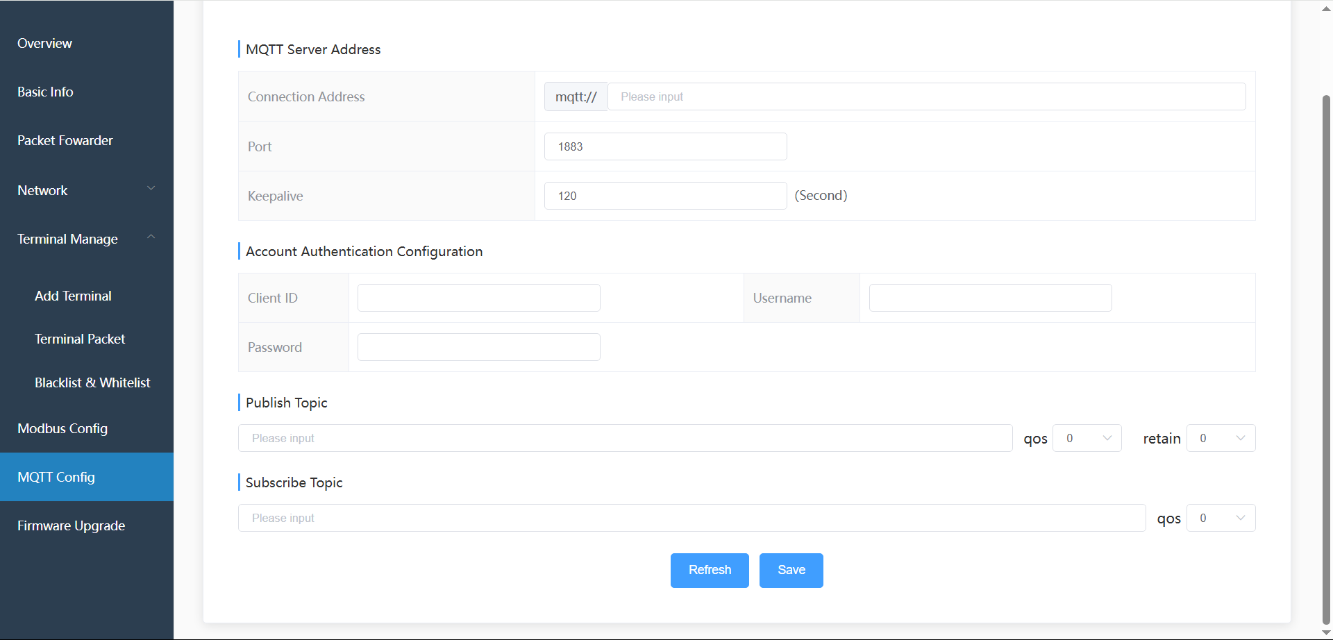
Go to the MQTT page to report gateway data to an MQTT server.
12.1 Server Information
- Server address: the host address of the MQTT server. The page automatically adds the mqtt protocol prefix.
- Port: the port of the MQTT server.
- Keepalive: the connection keepalive time (in seconds), used to maintain a long connection with the server.
12.2 Account Authentication (if required by the server)
- Client ID: the client identifier; it should remain unique on the same server.
- Username: the username used to connect to the server.
- Password: the password used to connect to the server.
12.3 Publish Topic
- Publish topic: the topic used by the gateway to report data to the server.
- QoS: message quality of service; options are 0, 1, and 2 (higher values mean higher reliability but more overhead).
- retain: whether to retain messages; 0 means not retained, 1 means retained.
12.4 Subscribe Topic
- Subscribe topic: the topic the gateway listens to when receiving data from the server.
- QoS: subscription quality of service; options are 0, 1, and 2.
After filling in, click Save. If the gateway cannot connect to the MQTT server, check the server address, port, account/password, topic names, and network connectivity.
13. Firmware Upgrade
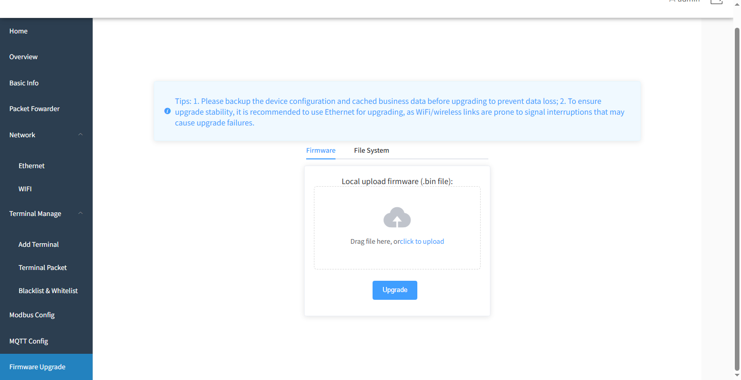
Go to the Firmware Upgrade page to upgrade the gateway firmware or file system.
13.1 Firmware Upgrade
- On the Firmware tab, select or drag in the firmware file (.bin).
- Click Upload, confirm, and the upgrade starts.
- Wait for the upgrade to complete. Do not power off or close the page during the process.
13.2 File System Upgrade
- Switch to the File System tab.
- Select or drag in the file system upgrade file (.bin).
- Click Upload, confirm, and the upgrade starts.
13.3 Upgrade Notes
- Before upgrading, export and save the current configuration first.
- It is recommended to upgrade over an Ethernet connection to avoid upgrade failure caused by an unstable wireless link.
- During the upgrade, do not power off, restart the device, or close the browser.
- After the upgrade, the device may restart automatically; wait for the device to come back online.
14. Remote Management
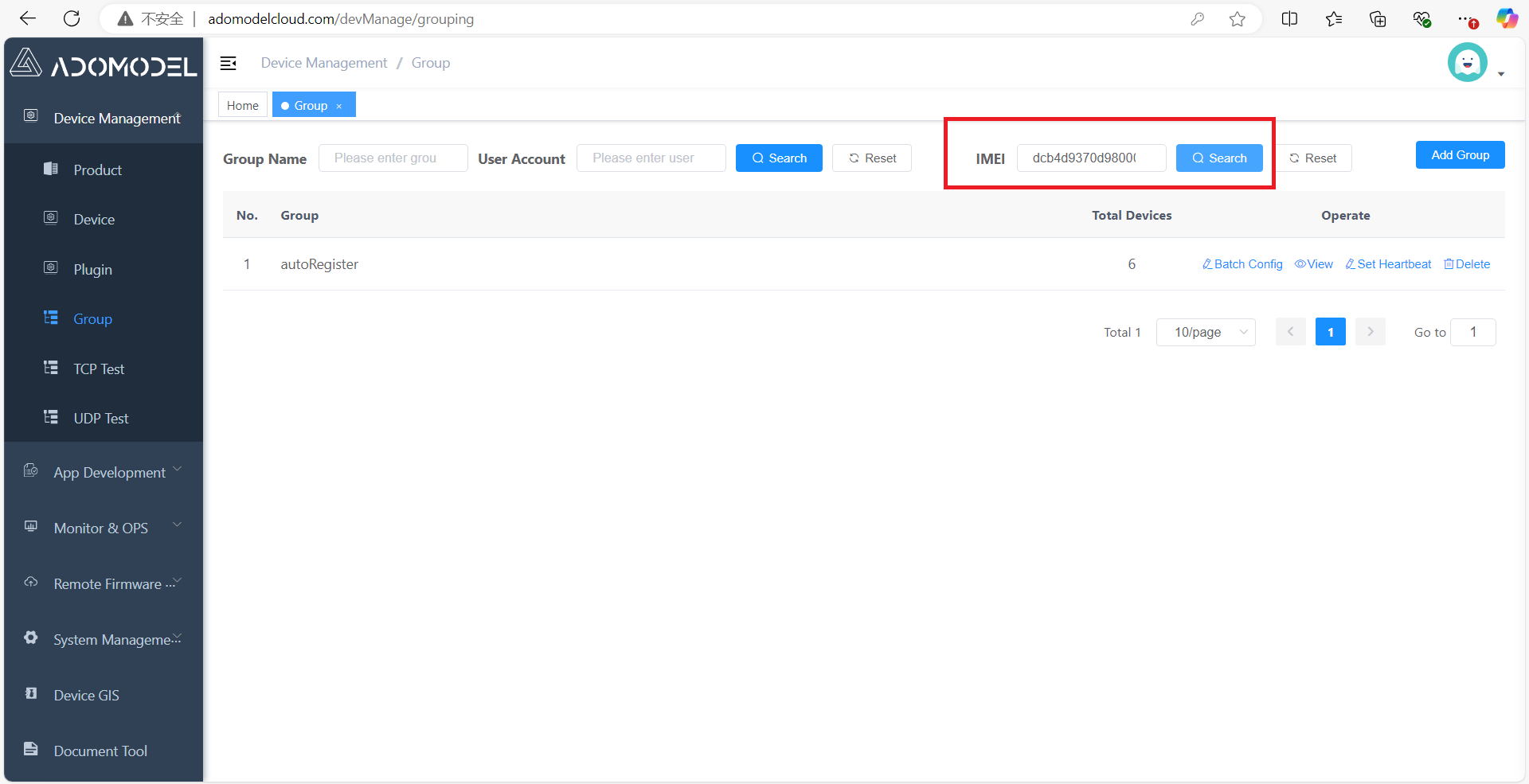
- Log in to the management platform at http://adomodelcloud.com/.
- In the Group menu, enter the first 15 digits of the gateway's IMEI in the IMEI field to find your gateway device.
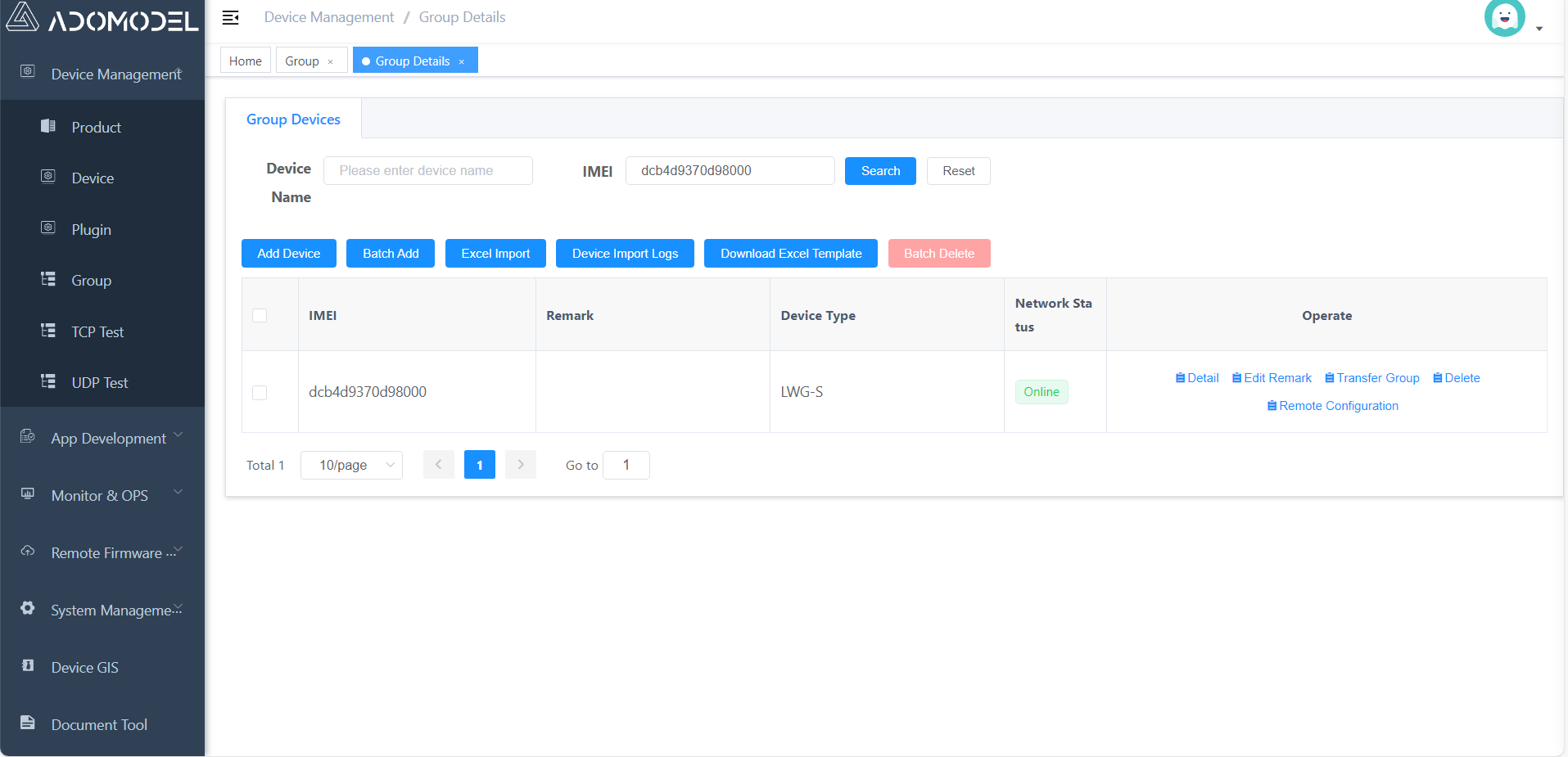
- Open Remote Connection Configuration and click Enable Remote Connection.
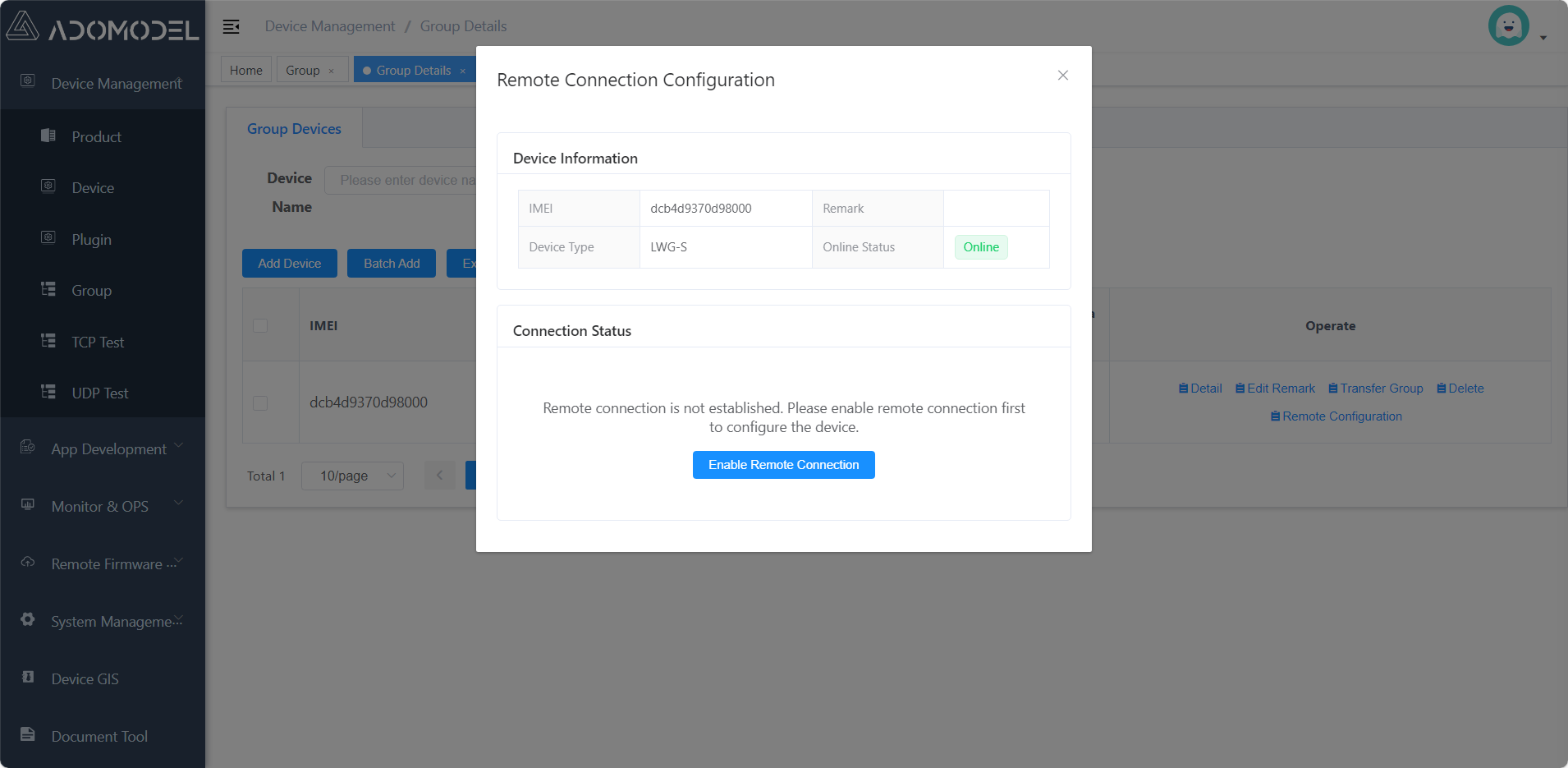
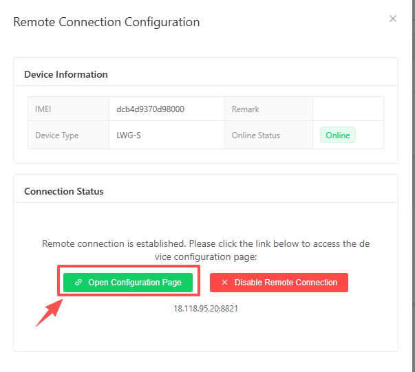
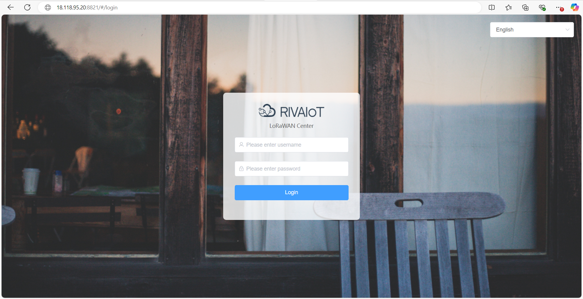
- Click Open Configuration Page to jump to the smart gateway login page. After logging in, you can configure the device.