LGW-M / LGW-L Gateway Web Configuration Guide
AdoModel Tech Inc. — Web configuration guide for the LGW-M / LGW-L indoor and outdoor LoRaWAN gateways.
Document Revision History
| Revision | Date | Author | Reviewer | Description |
|---|---|---|---|---|
| 1.0 | 2025-12-09 | Chenshw | Zhangfg | Initial version |
| 1.1 | 2026-03-15 | Wudh | Zhangzhp | Added remote configuration and Ethernet local direct connection instructions |
| 1.2 | 2026-09-15 | E-comm | Zhangzhp | Added frequency band appendix; Micro-B interface naming; Delete LGW915L LED |
1. Gateway Introduction
This chapter introduces the LGW-M / LGW-L indoor and outdoor LoRaWAN gateways, including the package contents, device appearance, and interface layout.
1.1 Package List
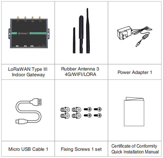
Indoor Gateway
- If you purchased a full-duplex gateway, an additional rubber antenna (LoRa) will be included.
- If any items are damaged, missing, or if you have other accessory requirements, please contact your distributor or sales representative promptly.
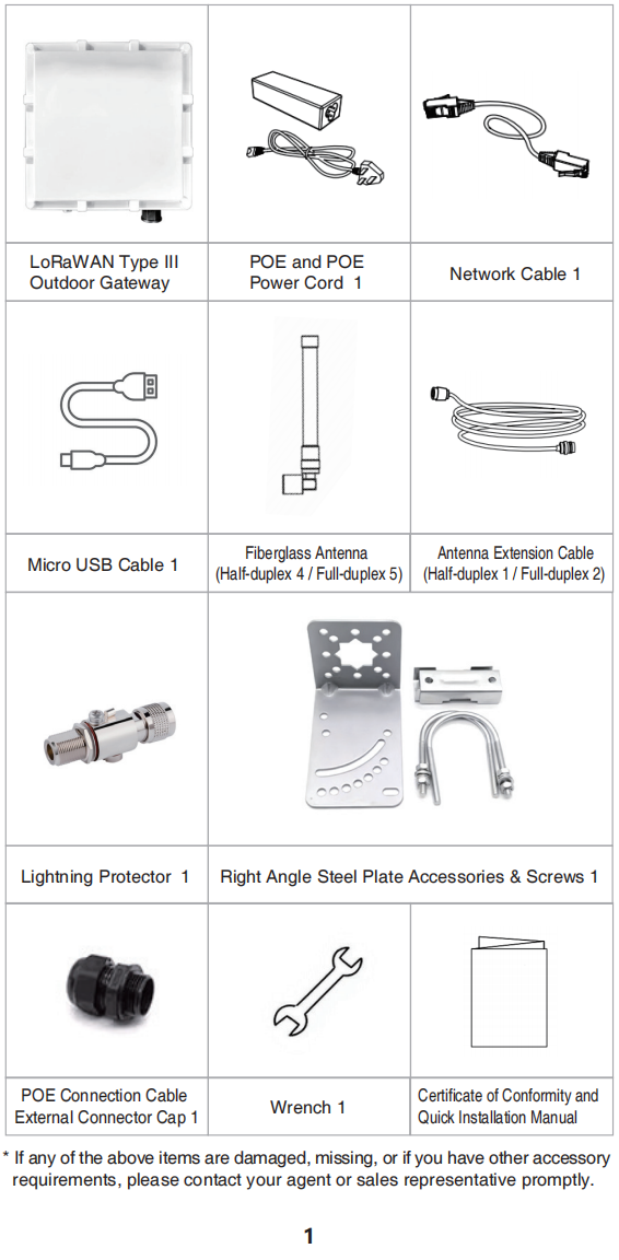
Outdoor Gateway
- If any items are damaged, missing, or if you have other accessory requirements, please contact your distributor or sales representative promptly.
1.2 Appearance
Indoor Gateway Appearance
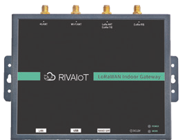
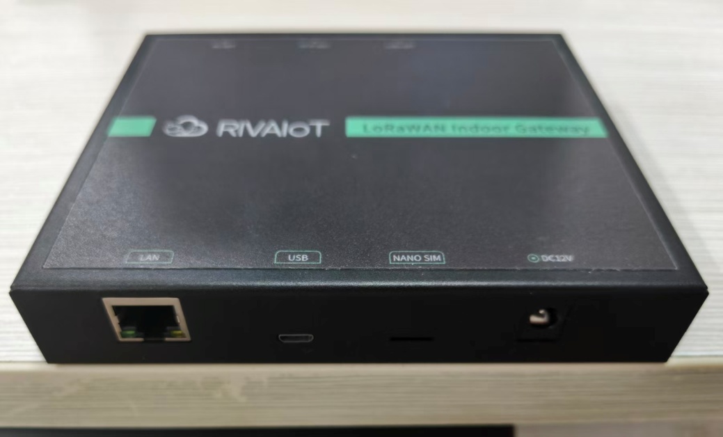
The device features a minimalist square design with smoothly rounded corners and a solid black iron housing. The surface is treated with a fine sandblasting process, providing a refined metallic texture and durability. The front panel is a unified flat surface with the brand logo and product model clearly printed in the center, with no unnecessary physical buttons. The bottom side of the device houses the interface area, providing an Ethernet port, USB port, SIM card slot, and DC 12V power port. All ports are neatly arranged, keeping cable connections tidy. The device supports both desktop placement and wall-mount installation, allowing flexible deployment on desks, walls, or in wiring cabinets. The overall design is understated and professional, suitable for wiring cabinets, server rooms, and industrial indoor environments, balancing practicality and space efficiency.
Outdoor Gateway Appearance
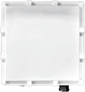
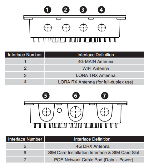
The device features an industrial-grade outdoor protection design, with a housing made of high-strength materials offering excellent waterproof and dustproof capabilities, capable of handling various complex outdoor environments. The housing structure is compact and sturdy, with all interfaces and screws treated for corrosion and rust resistance, ensuring reliability and durability for long-term outdoor use. The device supports pole-mount and wall-mount installation options, allowing flexible deployment on rooftops, light poles, exterior walls, and other outdoor scenarios. The overall design is robust and stable, balancing functionality and environmental adaptability, fully meeting the requirements for outdoor LoRaWAN network coverage deployment requirements.
1.3 Interface Description
Indoor Gateway
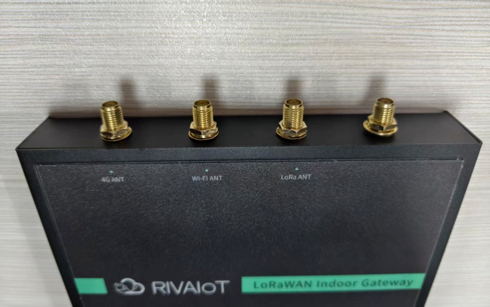
The top side of the device features antenna interfaces, from left to right:
- 4G Antenna Interface
- Wi-Fi Antenna Interface
- LoRa Antenna Interface (Full/Half-Duplex)
- LoRa Antenna Interface (Full-Duplex)
The bottom side of the device features functional interfaces, from left to right:
| Port | Description |
|---|---|
| Ethernet Port | Standard wired network interface for connecting to routers and switches, enabling LAN and cloud data transmission. The port has a dual-color status indicator: solid green indicates normal physical connection; flashing yellow indicates active data transmission. |
| Micro-B | Dual-function port: auxiliary power supply, can use a mobile phone Type-C charging cable to temporarily power the gateway; debug serial port, when connected to a computer can read device operation logs and debug device parameters locally. |
| SIM Card Slot | Used for inserting a Nano SIM card to provide the gateway with 4G cellular network connection, serving as a backup link for the wired network (LAN Port). It can also enable standalone deployment and data transmission in environments without Ethernet. (Note: The gateway does not support hot-plugging. Please power off the device before inserting/removing the SIM card.) |
| DC Power Jack | Main power supply interface, compatible with the included DC power adapter, input specification 12V/2A, providing primary power for stable device operation. |
Outdoor Gateway
2. Connecting Devices
2.1 Connecting via USB
- Locate the gateway's reserved Micro USB interface (for the outdoor gateway, the Micro USB interface is located below the SIM card slot).
- Use the included Micro USB cable, connect one end to the gateway and the other end to a computer.
- Enter the default gateway address in the computer browser's address bar:
192.168.0.100:8088, then press Enter to access the gateway's web configuration login page.
2.2 Connecting via Ethernet Cable
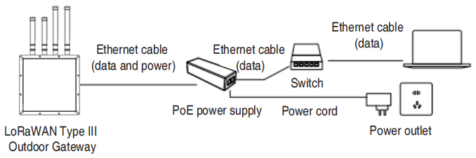
- Connect the gateway's Ethernet port to the LAN: Use the included Ethernet cable to connect to an available LAN port (for the outdoor gateway, connect to the POE & Ethernet adapter's port).
- The gateway defaults to DHCP mode to automatically obtain an IP address. Please ensure that the connected network has DHCP service enabled.
- Power on the gateway and wait approximately 40 seconds for the device to complete startup and obtain an IP address.
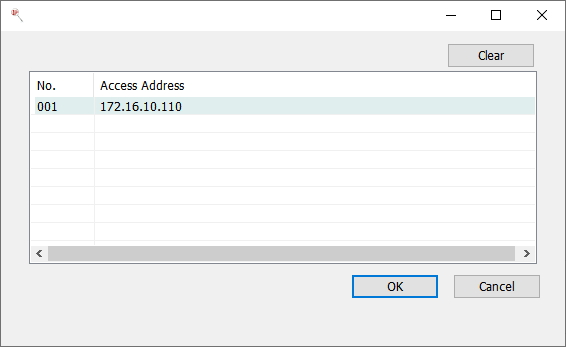
- On a computer connected to the same LAN, open the supplied LoraGW_IPScan tool to search and obtain the gateway's IP address. LoraGW_IPScan can be downloaded from www.adomodeltech.com or obtained from your account manager.
- Enter "IP Address:8088" in the browser address bar to access the gateway's web configuration login page.
For example: if LoraGW_IPScan shows the gateway IP as 172.16.10.107, enter 172.16.10.107:8088 in the browser to access.
2.3 Direct Local Ethernet Connection
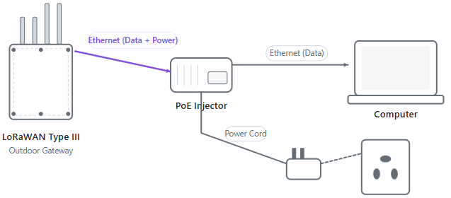
- Use the included Ethernet cable to connect the local computer's network port to the gateway's Ethernet port (for the outdoor gateway, connect to the POE & Ethernet adapter's corresponding port).
- After connecting, power on the gateway and wait approximately 3 minutes for the gateway to automatically assign an IP address.
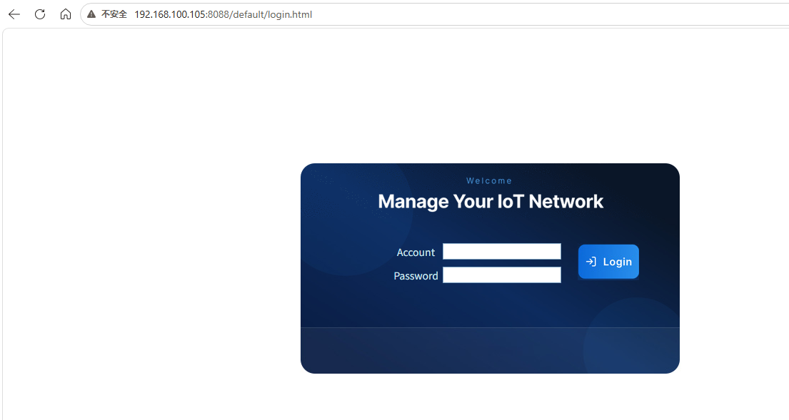
- Once the local computer obtains a valid IP address, open a web browser and enter the gateway's server mode access address in the address bar.
- Default server mode address:
192.168.100.105:8088. Server mode IP supports custom configuration. See "4.2 Ethernet Configuration" for details. - Press Enter in the browser address bar to access the gateway's web configuration login page.
2.4 Connecting via Remote Configuration
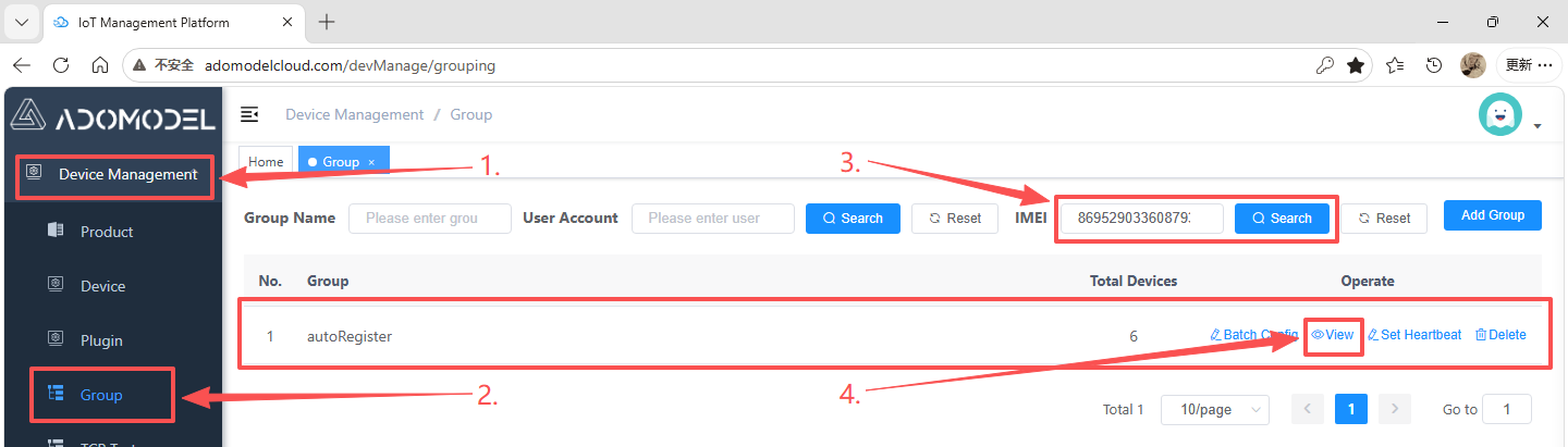
After the device is connected to the internet (via SIM card dial-up, Ethernet, or Wi-Fi STA mode connecting to an external hotspot), log in to our company's device management platform (domain: http://adomodelcloud.com/; account credentials can be obtained by contacting your distributor or sales representative). After successful login, follow these steps:
- Click the Device Management button to expand the submenu.
- Click the Group button.
- Enter the device IMEI and click the Query button. The results will be displayed below.
- In the results, click the View button to display the device details.
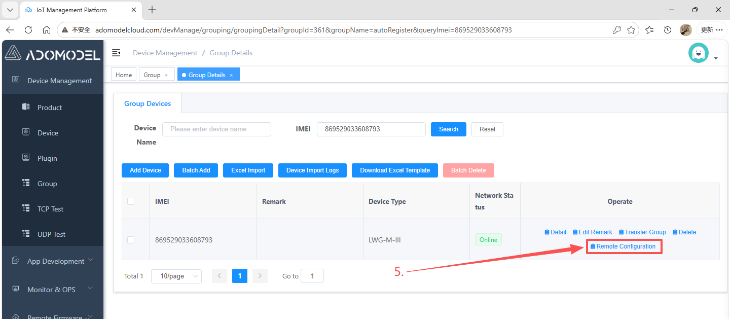
- In the action column, click the Remote Configuration button to enter the remote connection configuration page.
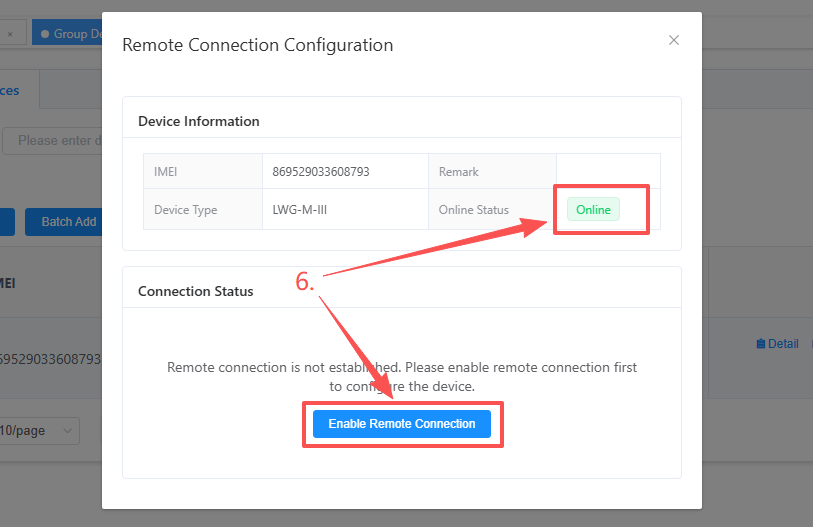
- Ensure the device status is "Online", then click the Enable Remote Connection button.
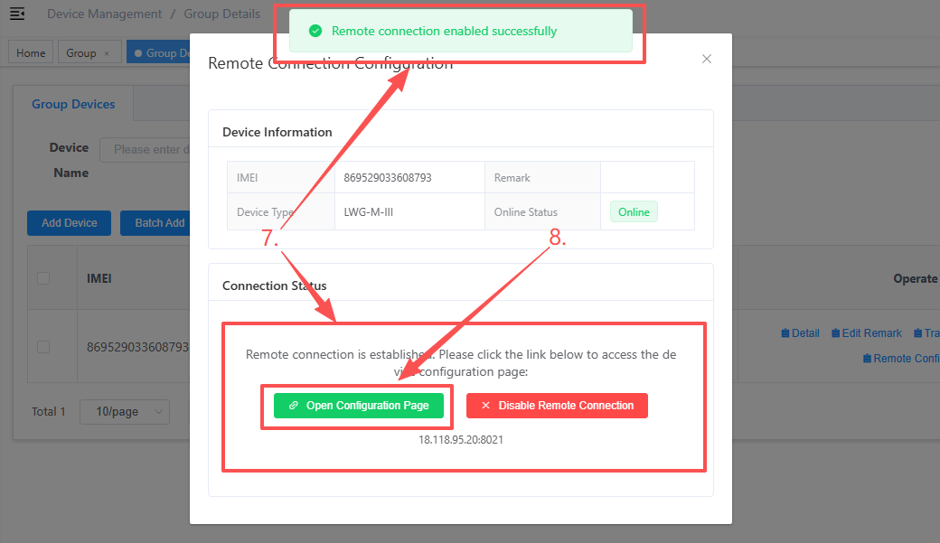
- Wait for remote configuration to be enabled. Upon success, a popup will appear with two buttons: Open Configuration Page and Close Remote Connection.
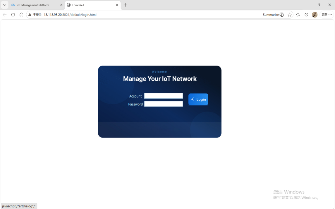
- Click the Open Configuration Page button to automatically redirect to the web login page.
3. Gateway Web Login Page
3.1 Login Page
After properly connecting the gateway device, use the corresponding IP address to access the gateway web page via a computer browser. USB access example: http://192.168.0.100:8088.
3.2 Default Account and Password
The login page displays the Current Firmware Version. The default login credentials are as follows:
| Item | Value |
|---|---|
| Default username | root |
| Default password | admin |
4. Device Management
4.1 Device Information
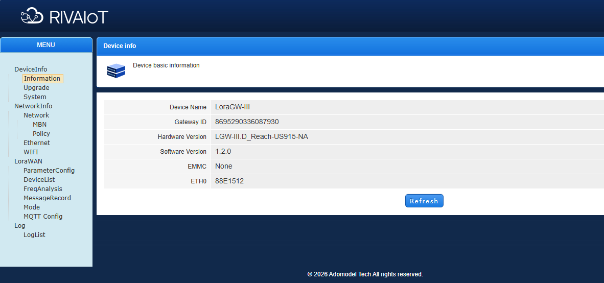
This page displays device basic information, device name, gateway ID, hardware/software versions, etc.
4.2 Device Upgrade (Local)
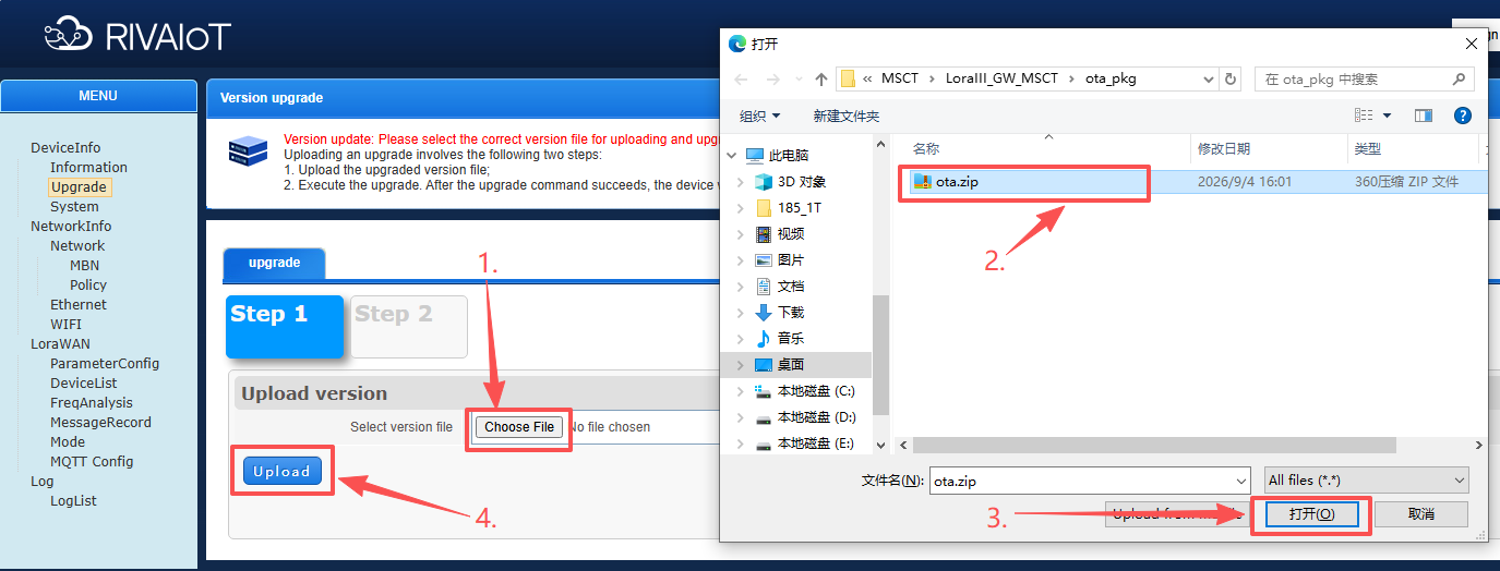
This interface can be used for device upgrade operations locally (or via remote configuration). Follow these steps in order:
- Click Select File.
- In the dialog, navigate to the upgrade package path and select the required package.
- Click Open.
- Click Upload.
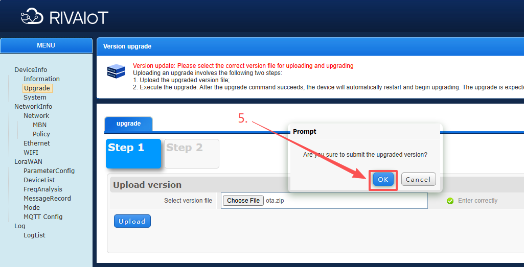
- Click Confirm in the upload confirmation dialog and wait for the upload to complete.
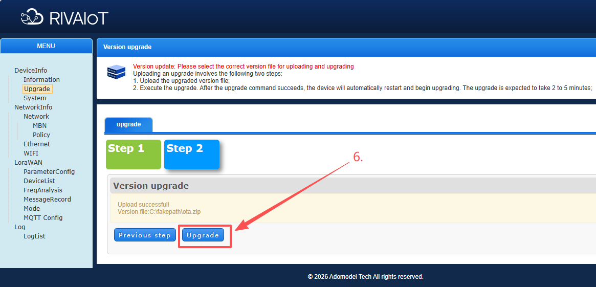
- After upload is complete, the page will redirect to Step 2. Click Upgrade and the device will restart immediately.
- Wait for the upgrade to complete. The entire process takes approximately 2-5 minutes.
4.3 Device Settings
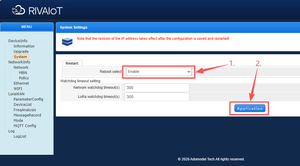
The system settings page allows you to restart the device and configure the watchdog timeout period.
Restart: Select "Enable" from the dropdown and click "Apply" to restart the device immediately.
5. Network Management
5.1 Mobile Network Configuration
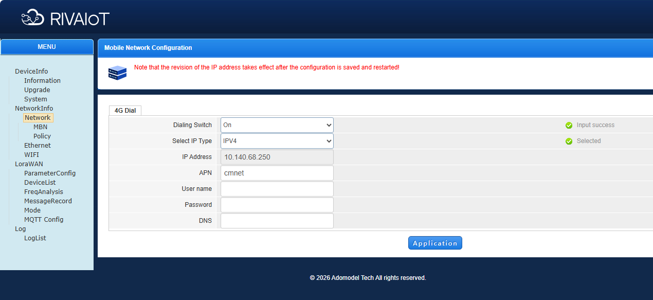
After inserting an active 4G SIM card and powering on, the device will automatically dial up to access the internet.
If the 4G card has special restrictions, you can configure 4G network parameters as needed. If no special APN is required, keep the default settings.
MBN Configuration
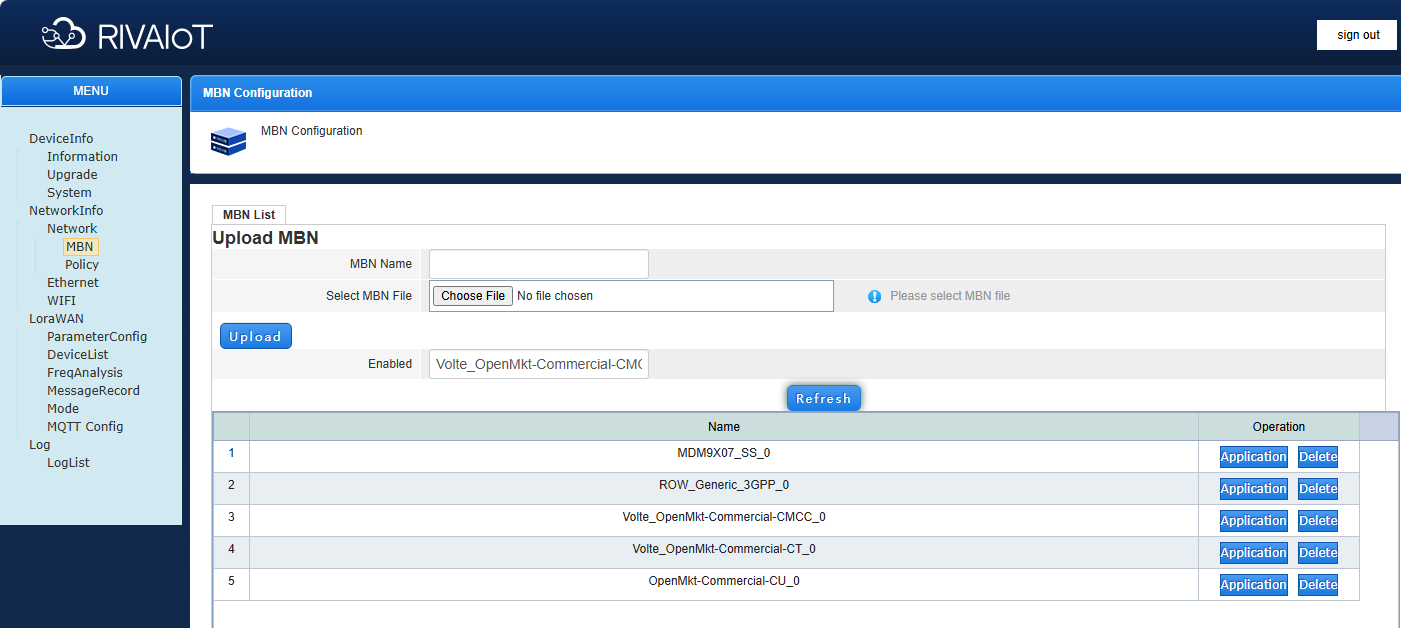
This interface supports MBN management operations, including adding/deleting MBNs, viewing the MBN list, and modifying the active MBN.
Network Connection Strategy
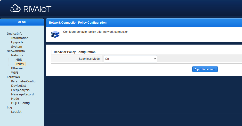
This interface configures the behavior policy after network connection.
Seamless Switching Mode: When enabled, the device maintains network connection when switching between TDD and FDD networks, without triggering reconnection.
5.2 Ethernet Configuration
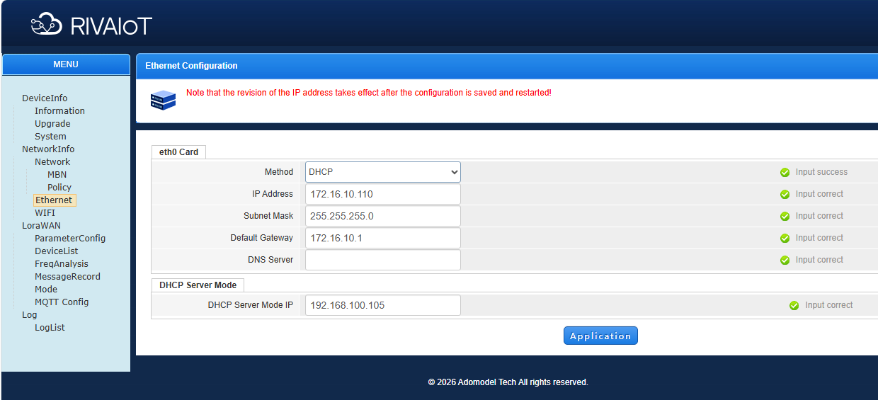
When using a PoE device for Ethernet connection, this page is used to configure the Ethernet mode, with DHCP or Static IP options.
If the device fails to connect via Ethernet IP, it will restart Ethernet in server mode. In this mode, the IP address in the DHCP server mode IP field will be set as the gateway's Ethernet IP, and devices on the same subnet will be assigned IP addresses.
5.3 Wi-Fi Connection
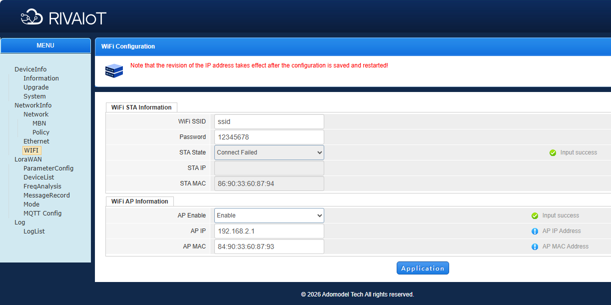
To connect to a router, enter the Wi-Fi name and password in the Wi-Fi STA information section. The device will restart after saving.
6. LoRaWAN Management
6.1 Parameter Configuration
The parameter configuration under LoRaWAN Management is the core configuration of the gateway. Frequency points are configured at the factory based on customer requirements. If you have custom requirements, you can modify them on this configuration page.
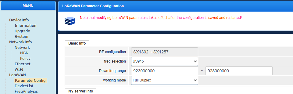
Basic Information
Configure the gateway's frequency band and operating mode.
NS Server Information
Configure the server address and uplink/downlink ports. Refer to the appendix "LoRaWAN Frequency Bands and Custom Frequency Points".

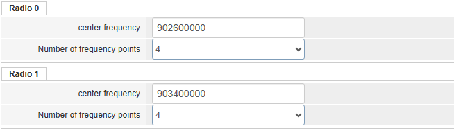
Center Frequency Setting (Full-Duplex)
Set the center frequency of the operating band. Refer to the appendix "LoRaWAN Frequency Bands and Custom Frequency Points".
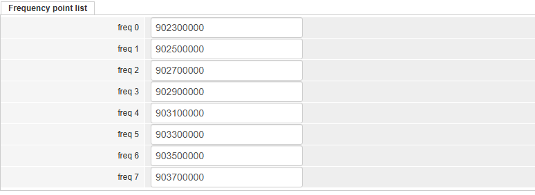
Frequency Point List
Configure detailed frequency band data. Refer to the appendix "LoRaWAN Frequency Bands and Custom Frequency Points".
Power Configuration
Set the transmission power. It is recommended to keep the default settings.

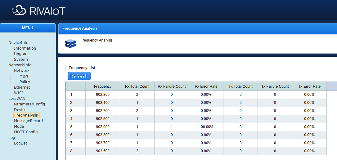
6.2 Frequency Point Analysis
Analyze and statistics of frame loss rate for gateway frequency points.
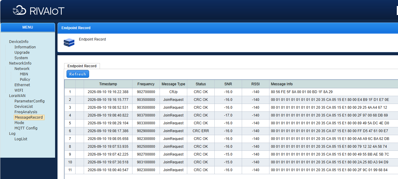
6.3 Packet Log
Record gateway packets.
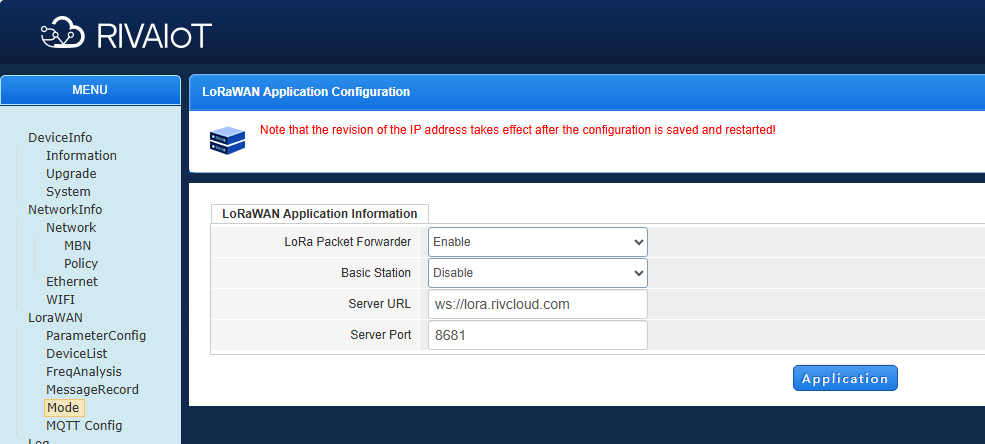
6.4 Startup Method
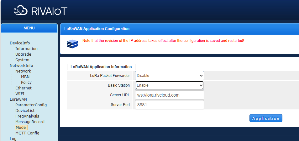
The Startup Method page allows you to configure whether to start Basic Station.
7. BasicStation Parameter Configuration
On the web page, select the following configuration:
lora_pkt_fwd: disableBasicStation: enableServer_url: Can be modified according to the server address.Server_port: Determined by the target server port.
After confirmation, click Application. You can refresh the page to view the configuration result.
8. Built-in NS Startup
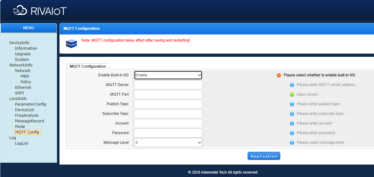
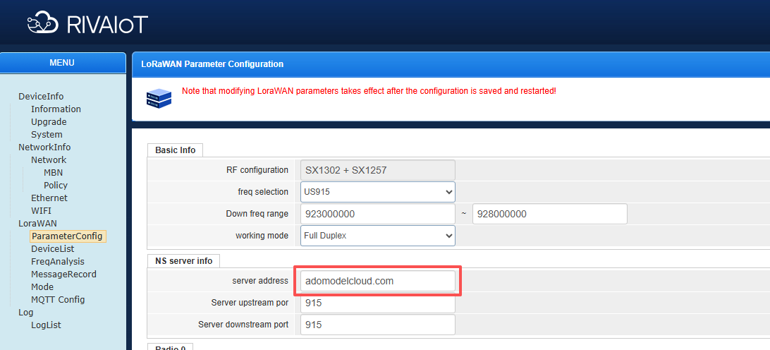
If an external server is not required, you can use the device's built-in NS server. Set the built-in NS to enabled, change the server address to 127.0.0.1 in the parameter settings, and click Apply. After confirming the parameters are correct, restart the device for the changes to take effect.
Other MQTT parameters can be left blank and default to empty. To send uplink data to a third-party platform, fill in the relevant information and restart the device for the changes to take effect.
9. Log Management
9.1 Log List
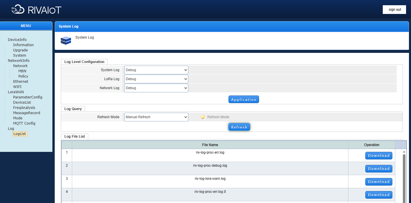
Manage device log information. You can configure log levels or export device logs through this interface.
Appendix: LoRaWAN Frequency Bands and Custom Frequency Points
This appendix lists the LoRaWAN frequency bands supported by the gateway and the default ports used by the platform for each band. The gateway is factory-configured per order; only modify the frequency plan when your network requires it.
Table 1 — Supported frequency bands
| Region | Band | Parameter |
|---|---|---|
| China | CN470 | CN_470-510 |
| Europe | EU433 | EU_433 |
| Europe | EU868 | EU_863-870 |
| North America | US915 | US_902-928 |
| Australia | AU915 | AU_915-928 |
| India | IN865 | IN_865 |
| Asia-Pacific | AS923 | AS_923 |
Multiple bands are available depending on the hardware variant: EU433 / CN470 / IN865 / EU868 / US915 / AU915 / AS923-1&2&3&4.
Table 2 — Default platform ports by band
| Band | Port |
|---|---|
| CN470 | 470 |
| EU433 | 433 |
| EU868 | 868 |
| US915 | 915 |
| AU915 | 1915 |
| IN865 | 865 |
| AS923 | 923 |
For external network servers, set the uplink and downlink ports to the values required by your server. For the built-in NS, use the built-in server address 127.0.0.1 with the ports specified in the gateway documentation.
Notes on custom frequency points
- Basic Information (band and operating mode), NS Server Information (server address and uplink/downlink ports), Center Frequency Setting (full-duplex models), Frequency Point List, and Power Configuration are all configured under LoRaWAN Management → Parameter Configuration.
- Frequency points must match the configuration of your end nodes and network server. Incorrect frequency configuration may prevent terminals from joining the network or communicating normally.
- If you are unsure about a parameter, keep the factory default or contact technical support.