LGW915SH Quick Start Guide
LoRaWAN Mini Indoor Gateway
1. Product Overview
1.1 What Is This Product?
The LGW915SH is a mini indoor IoT gateway built on LoRaWAN® low-power wide-area network (LPWAN) technology. Supporting global LoRaWAN frequency bands, it connects up to 100 LoRaWAN end nodes and quickly establishes a LoRaWAN low-power private network for small industrial environments, with a coverage range of up to 500 m.
With built-in LoRa and Wi-Fi antennas in a compact housing, the gateway connects to the wide area network via Wi-Fi or Ethernet and forwards node data to the cloud, enabling remote IoT data monitoring. It is designed for small industrial environments such as workshops, warehouses, and small plants.
The gateway uploads data to the cloud via Wi-Fi or wired Ethernet. It is compatible with mainstream LoRaWAN network servers (such as ChirpStack and The Things Stack), and also provides a built-in network server (NS) with on-gateway terminal management, so you can deploy your own IoT applications quickly and flexibly. In this guide, the gateway is used with the AdoModel LoRaWAN NS cloud platform (http://adomodelcloud.com:4560/).
Key features at a glance:
- Global LoRaWAN bands, up to 100 nodes — 8-channel full-duplex SX1302 transceiver, connects up to 100 LoRaWAN end nodes.
- Built-in antennas — LoRa and Wi-Fi antennas integrated; nothing to install.
- Private LoRaWAN network in minutes — coverage up to 500 m, ideal for small industrial sites.
- Built-in NS with terminal management — add OTAA/ABP end devices directly on the gateway.
- Flexible backhaul — Wi-Fi (2.4 GHz only) or wired Ethernet.
- Open ecosystem — works with mainstream LoRaWAN network servers, the built-in NS, or third-party IoT platforms.
1.2 Where the Gateway Fits in Your System
The gateway is one link in a complete data chain. Figure 1 shows a typical AdoModel IoT deployment and the role of each component.
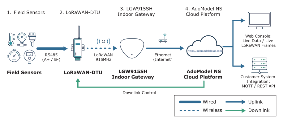
How data flows through the system
- Uplink: field sensors report their readings over an RS485 cable to a LoRaWAN-DTU, which packages the data into LoRaWAN frames and transmits them over the air. The gateway receives these radio signals and forwards them — via Wi-Fi or wired Ethernet — to the cloud, where the AdoModel LoRaWAN NS platform decodes them into application data.
- Downlink: commands sent from the platform travel the reverse path. The gateway transmits them over the air to the DTU, which outputs them through its RS485 port to the sensor or controller.
The role of each component
| Component | Role in the system |
|---|---|
| Field Sensor | Measures physical quantities (temperature, pressure, flow, etc.) and outputs data through its RS485 interface. |
| LoRaWAN-DTU | The translator between sensors and the wireless world: converts RS485 data to LoRaWAN radio frames, and vice versa. |
| LGW915SH Gateway | The relay station between wireless and the Internet: receives LoRaWAN radio frames from end nodes and forwards them to the cloud over Wi-Fi or Ethernet. |
| AdoModel LoRaWAN NS Platform | The brain of the network: manages gateways and devices, decodes application data, and provides web console, downlink control, and MQTT / REST API integration. |
1.3 What This Guide Helps You Accomplish
This guide walks you through everything needed to get a single gateway from the box to a working connection with the AdoModel LoRaWAN NS platform. Follow the chapters in order; by the end you will have:
- unpacked and verified the shipment (Chapter 2);
- familiarized yourself with the interfaces and indicators (Chapter 3);
- powered the gateway and connected it to the Internet via Ethernet or Wi-Fi (Chapters 4–5);
- opened the gateway web console and verified its platform connection settings (Chapters 6–7);
- seen the gateway appear online on the AdoModel LoRaWAN NS platform (Chapter 8);
- learned what the platform can do for you once the gateway is online (Chapter 9).
If anything does not work as described, turn to Chapter 10 (Troubleshooting).
Connecting end-node devices (e.g., a LoRaWAN-DTU with sensors) to the network is covered in a companion document, the LoRaWAN-DTU Quick Start Guide.
The gateway itself never interprets your sensor data — it simply relays LoRaWAN frames. All intelligence (decoding, device management, integrations) lives in the NS platform. This separation is what allows one gateway to serve thousands of heterogeneous devices.
2. Packing List
Unpack the box and verify the shipment contains the following items:
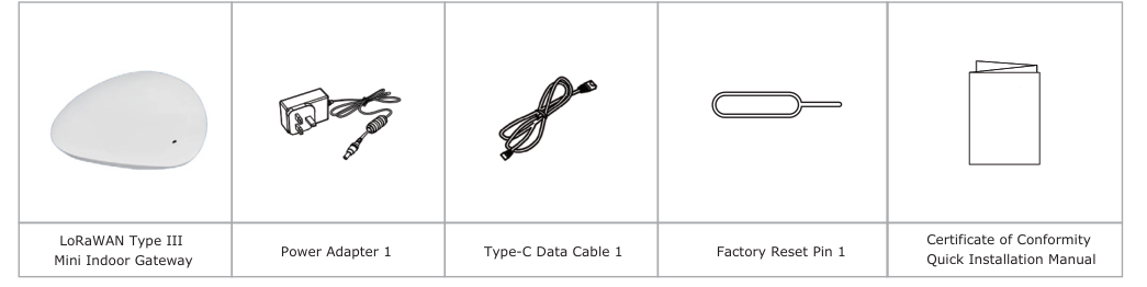
- LoRaWAN Type III Mini Indoor Gateway ×1
- Power Adapter ×1
- Type-C Data Cable ×1
- Factory Reset Pin ×1
- Certificate of Conformity
- Quick Installation Manual
All antennas are built into the gateway — there is nothing to screw on. If any items are damaged or missing, or if you have other accessory requirements, please contact your agent or sales representative promptly.
3. Interfaces and Indicators
The interfaces are arranged on the rear of the device. Figure 2 shows the layout; the tables below list each interface and indicator.
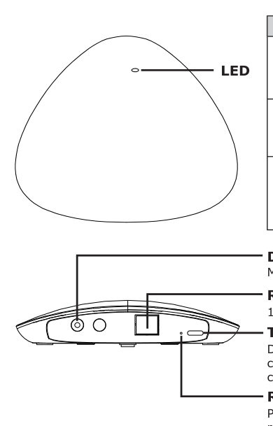
Interface definitions
| Interface | Description |
|---|---|
| DC power jack | Main power input, 12 V / 2 A, with the included adapter. |
| RJ45 Ethernet port | 10/100 Mbps wired network interface for routers or switches; dual-color status. |
| Type-C port | Dual function: auxiliary power (temporary power via a phone charging cable) and debug serial port (read device logs / debug parameters from a computer). |
| Reset pinhole | Press and hold with the supplied pin (or a toothpick) for 5 seconds to restore factory settings; all network and device configurations are cleared. |
Status indicators (LED)
| LED | Color & function | Meaning |
|---|---|---|
| Red | System power & basic operation | Solid: powered on, running normally; Off: not powered, or power fault; Blinking slow: booting or factory reset in progress; Blinking fast: system fault or critical error. |
| Green | IP network connection | Solid: IP address obtained, network connected; Off: network not connected or not enabled; Blinking: trying to connect (Wi-Fi / Ethernet searching or dialing). |
| Blue | LoRaWAN service | Solid: Packet Forwarder running, connected to the LoRaWAN network server; Off: LoRaWAN module not started, or no network server configured; Blinking: receiving or sending LoRa packets (RF activity). |
After power-on, a solid red indicator with the green indicator off or blinking means the gateway is ready for first-time configuration through the gateway hotspot (Section 6.1). The green indicator turns solid once the network connection is established.
4. Installation and Power
No special tools are required. The gateway needs no antenna installation.
4.1 Powering the Gateway
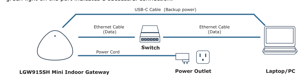
- Plug the included power adapter into the DC jack on the rear of the gateway and into a wall outlet.
The device supports desktop placement and wall mounting.
The Type-C port can be used for temporary backup power with a phone charging cable, but the DC adapter is the primary power supply.
4.2 Connecting the Network (choose the backhaul)
Choose a backhaul for the network connection:
- For Ethernet backhaul: connect a network cable from your router or switch to the RJ45 port. A solid green light on the port indicates a successful connection (Figure 3).
- For Wi-Fi backhaul: no cable needed — configure the Wi-Fi connection on the gateway web console (Chapter 6 → Network → WiFi).
4.3 Reset (if needed)
- Use the supplied factory reset pin to press and hold the reset pinhole for 5 seconds. The device is restored to factory settings and all configurations are cleared.
Factory reset clears all network and device configurations. Export a backup of the configuration first if possible (web console → Export Configuration).
5. Power On & Network Backhaul
The gateway supports three backhaul options:
| Backhaul | Best for | What to do |
|---|---|---|
| Wi-Fi | Sites without a wired network outlet near the gateway. | Connect to the gateway’s setup hotspot (Section 6.1), then configure the gateway to join your local Wi-Fi (STA mode) on the web console. 2.4 GHz networks only — 5 GHz Wi-Fi is not supported. |
| Ethernet (recommended) | Installations with a wired network available. | Connect the Ethernet cable (Section 4.2) — the gateway obtains an IP address automatically (DHCP). No further configuration is needed. |
5.1 Post Power-On Checks
- The power adapter is connected and the device is powered.
- The Ethernet cable is firmly seated (if used); the Ethernet port LED is solid green.
- The green status indicator is solid once the gateway has obtained an IP address and the network connection is up.
Once powered and connected to the Internet, the gateway automatically starts sending data to the NS platform. In a good network environment the gateway comes online within 1–3 minutes of power-on (up to ~5 minutes). You will verify this on the platform in Chapter 8, after checking the web console settings in Chapters 6–7.
6. Accessing the Gateway Web Console
The gateway is managed through a built-in web console. The mini indoor gateway differs from the other AdoModel models: its console is reached primarily through the gateway’s own Wi-Fi hotspot. There are three ways to reach it:
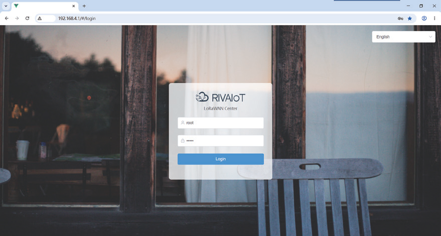
- Option 1 — Gateway Wi-Fi hotspot: connect your computer to the gateway’s built-in hotspot and open the console at 192.168.4.1. Works out of the box, no network infrastructure needed.
- Option 2 — Ethernet via your LAN: connect the gateway to your router or switch and look up its IP address with the supplied LoraGW_IPScan tool.
- Option 3 — Remote access via the CMP platform: if the gateway is already online, open its web console remotely through the AdoModel IoT Management Platform (CMP) without going on site.
6.1 Option 1: Gateway Wi-Fi Hotspot
For first-time setup, the gateway broadcasts a Wi-Fi hotspot with default settings:
| Item | Default value |
|---|---|
| Hotspot name (SSID) | LGW_XXXXXX (XXXXXX = digits of the MAC address) |
| Hotspot password | lgwwifipsw |
| Console address | http://192.168.4.1 |
| Username / password | root / admin |
- On your computer, find the gateway’s Wi-Fi hotspot and connect to it with the password above.
- Open a browser (Chrome recommended) and enter
http://192.168.4.1. - Log in with the default credentials:
root/admin.
6.2 Option 2: Ethernet via Your LAN
- Connect the gateway’s Ethernet port to your router or switch (Section 4.2).
- Make sure the network has DHCP enabled — the gateway obtains its IP address automatically.
- On a computer connected to the same LAN, use the supplied LoraGW_IPScan tool to find the gateway’s IP address. The tool can be downloaded from www.adomodeltech.com or obtained from your account manager.
- Enter the IP address in a browser to access the web console.
| Item | Default value |
|---|---|
| Username / Password | root / admin |
6.3 Option 3: Remote Access via the CMP Platform
This option requires the gateway to be already connected to the Internet (Ethernet or Wi-Fi) and shown as Online in CMP.
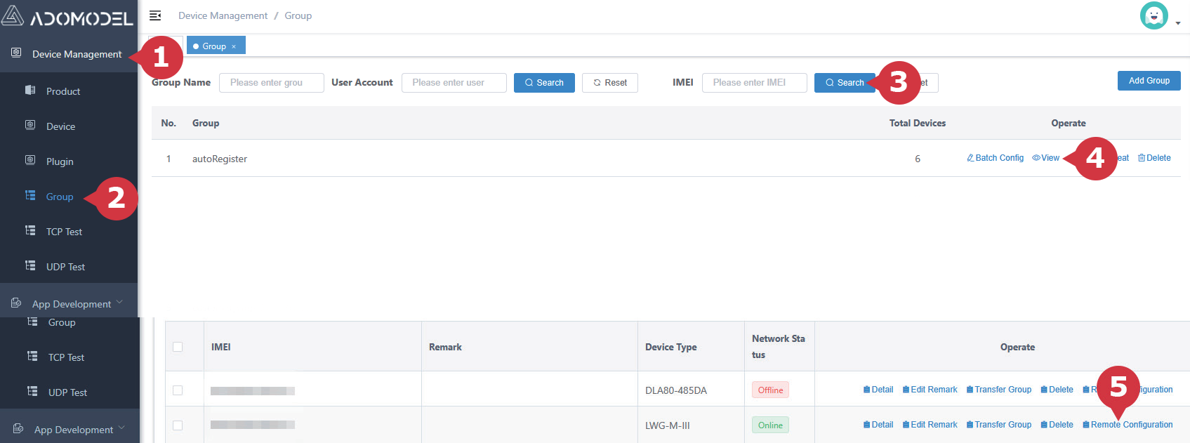
- Log in to the AdoModel IoT Management Platform (CMP): http://adomodelcloud.com/ (account provided by your account manager).
- Click “Device Management” to expand the menu, then click “Group”.
- Enter the gateway ID (IMEI) in the search box and click “Search”.
- Click “View” on the found device.
- Under the operation column, click “Remote Configuration” (Figure 5).
- Confirm the device status is “Online”, then click “Enable Remote Connection”. Wait until a dialog confirms success and shows the “Open Configuration Page” and “Close Remote Connection” buttons.
- Click “Open Configuration Page” — the gateway web console login page opens.
7. Connecting to the AdoModel Platform
7.1 Verifying the NS Settings
The gateway is factory-configured for the North American band (US915) and for the AdoModel LoRaWAN NS platform. In most cases you do not need to change anything — just verify that the settings match the table below.
- Open the gateway web console (Chapter 6).
- Go to “Gateway Configuration” → “NS Network Server Settings”.
- Verify the following values:
| Setting | Expected value (North America) |
|---|---|
| NS server address | adomodelcloud.com |
| Uplink port | 915 |
| Downlink port | 915 |
| Band | US915 (US_902-928) |
If any value differs, correct it and click Save. If the gateway cannot connect to the network server, check the server address, ports, firewall, and the gateway’s network connection.
7.2 Using the Built-in NS
The gateway also provides a built-in network server: set the server address to 127.0.0.1 with uplink port 1780 and downlink port 1782, and you can add OTAA/ABP end devices directly on the gateway (Terminal Management). This is useful for standalone deployments without a cloud platform. See the LGW-SH Gateway Web Configuration Guide for details.
7.3 Using a Different Network Server
If you operate your own LoRaWAN network server (e.g., ChirpStack or The Things Stack), enter its address and ports on the same page. Frequency-plan customization is beyond the scope of this guide — see the LGW-SH Gateway Web Configuration Guide.
If your gateway has not yet been registered on the platform, follow the registration procedure described in the companion LoRaWAN-DTU Quick Start Guide, or contact your account manager.
8. Verifying the Gateway Is Online
8.1 Log In to the NS Platform
- Open http://adomodelcloud.com:4560/ in your browser.
- Log in with the account provided by your account manager.
8.2 Check the Gateway Status
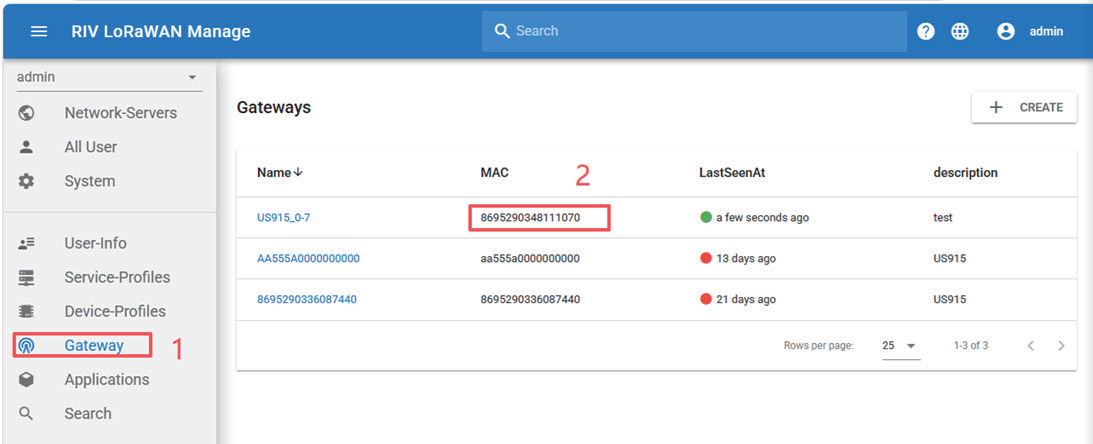
- Click the “Gateway” tab on the left side.
- Enter the gateway MAC ID in the “Search” box and locate your gateway (Figure 6). If it does not exist, click the “CREATE” button in the upper left corner to create it.
- Check the status dot:
- Green dot — the gateway is online and connected to the platform. You are done with this guide’s setup path; continue to Chapter 9 to learn what the platform offers.
- Red dot — the gateway is offline. After power-on (or a new registration), the gateway typically comes online within 1–3 minutes in a good network environment, and within about 5 minutes at most. If it is still offline after 5 minutes, see Chapter 10.
If the MAC ID on the label has 15 digits, append a “0” at the end to make 16 digits before entering it on the platform (e.g., 866999……7 → 866999……70).
8.3 Alternative Check via CMP
You can also confirm that the gateway has Internet access from the CMP platform (http://adomodelcloud.com/): search the gateway IMEI as described in Section 6.3; an “Online” status means the backhaul link works. If the gateway is online in CMP but offline on the NS platform, re-check the NS settings of Chapter 7.
9. What the Platform Can Do for You
Once your gateway is online, the AdoModel LoRaWAN NS platform is your window into the network. Highlights:
- Applications & device management — organize end-node devices into applications; register devices, manage activation keys (OTAA), and monitor device status.
- Live Data — view decoded application data from your devices in real time.
- Live LoRaWAN Frames — inspect raw LoRaWAN protocol frames (e.g., JoinRequest / JoinAccept) for network debugging.
- Downlink control — send commands to devices from the platform (e.g., through the downlink tool).
- Integration — retrieve your data via standard RESTful APIs and MQTT subscriptions for custom application development.
A quick end-to-end walkthrough — registering the gateway and a LoRaWAN-DTU node, and testing uplink/downlink data — is provided in the companion LoRaWAN-DTU Quick Start Guide. The complete platform documentation is available separately (AdoModel NS Platform User Guide).
10. Troubleshooting
| Symptom | Possible cause | What to do |
|---|---|---|
| Cannot find or connect to the gateway hotspot | Gateway not powered; too far away; hotspot disabled after STA configuration. | Check power and the red indicator (solid = powered on); move closer to the gateway. If the gateway has joined a local Wi-Fi network (STA mode) and the hotspot is off, use Ethernet or CMP remote access instead. |
| Web console page will not open (hotspot) | Wrong address; browser cache. | Confirm http://192.168.4.1; try Chrome; clear the browser cache. |
| Web console page will not open (CMP remote) | Gateway not Online in CMP. | Remote configuration only works when the gateway has Internet access. Use the hotspot method (Section 6.1) instead. |
| Login fails | Wrong credentials. | Use the defaults root / admin. If the password was changed and lost, use the reset pinhole (Section 4.3) to restore factory settings. |
| Gateway never comes online on the NS platform | No backhaul link; wrong gateway ID on the platform; NS settings mismatch. | 1) Check that the Wi-Fi/Ethernet link works (CMP status, Section 8.3). 2) Compare the gateway ID on the platform with the label on the device (mind the 15→16 digit rule). 3) Verify the NS settings (Chapter 7). 4) Power the gateway off for about 15 seconds and power it on again. |
| Wi-Fi backhaul does not connect | 5 GHz network; wrong password; weak signal. | The gateway supports 2.4 GHz networks only; check the SSID and password on the web console (Network → WiFi); improve signal strength or use Ethernet. |
For further assistance, contact your agent or sales representative, or visit www.adomodeltech.com.
Appendix A: Specifications
Key specifications of the gateway (from the LGW-L-III Product Specification; refer to the full specification sheet for details):
| Item | Specification |
|---|---|
| MCU | ESP32-S3 |
| Storage | 128 Mbit (16 M × 8) |
| LoRaWAN channels | 8 (full-duplex / half-duplex) |
| Frequency band | US915 |
| Receiving sensitivity | -143 dBm |
| Transmission power | Max. 30 dBm |
| LoRaWAN antenna | 2 built-in antenna interfaces, 50 Ω |
| LoRaWAN protocol | V1.0.4 and V1.0.2, Class A / C |
| Ethernet port | 1× 10/100 Mbps |
| Wi-Fi | 2.4 GHz 802.11 b/g/n only (5 GHz not supported); built-in antenna; client (STA) or AP mode |
| Other interfaces | Reset pinhole ×1; Type-C (aux power + debug) ×1; RGB status LED ×1 |
| Power supply | DC 12 V adapter (Type-C as temporary backup) |
| Power consumption | Avg. 3.4 W; peak 5 W |
| Casing | — |
| Operating temperature | -50 °C to +100 °C |
| Storage temperature | -50 °C to +100 °C |
| Relative humidity | 10%–90% RH, non-condensing |
| EMC protection | Contact discharge 4 kV; air discharge 8 kV |
| Installation | Desktop placement or wall mounting (indoor); coverage up to 500 m |
Appendix B: Default Parameters
| Parameter | Default value |
|---|---|
| Gateway hotspot SSID | LGW_XXXXXX (digits of the MAC address) |
| Gateway hotspot password | lgwwifipsw |
| Web console address (hotspot) | http://192.168.4.1 |
| Web console username / password | root / admin |
| Ethernet mode | DHCP |
| NS server address (external) | adomodelcloud.com |
| NS uplink / downlink port (external) | 915 / 915 |
| Built-in NS | 127.0.0.1, uplink 1780 / downlink 1782 |
| Band | US915 |
| NS platform web address | http://adomodelcloud.com:4560/ |
| CMP platform web address | http://adomodelcloud.com/ |
Regulatory Compliance
FCC ID: 2BWC6LGW915SH
This device complies with Part 15 of the FCC Rules. Operation is subject to the following two conditions: (1) this device may not cause harmful interference, and (2) this device must accept any interference received, including interference that may cause undesired operation.
RF Exposure: This equipment complies with FCC radiation exposure limits set forth for an uncontrolled environment. The antennas must be installed to provide a minimum separation distance of at least 20 cm from all persons, and must not be co-located or operating in conjunction with any other antenna or transmitter, except in accordance with FCC multi-transmitter product procedures.
Caution: Any changes or modifications to this device not expressly approved by the manufacturer could void the user’s authority to operate the equipment.
Download the PDF
This page is also available as a printable PDF document.
Download PDF