LGW915M Quick Start Guide
LoRaWAN Type III Outdoor Gateway — Get started from unboxing to a working network connection.
1. Product Overview
1.1 What Is This Product?
The LGW915M is an outdoor IoT gateway built on LoRaWAN® low-power wide-area network (LPWAN) technology. It integrates Semtech’s high-performance SX1302 8-channel transceiver, supports full-duplex operation, and can serve thousands of end-node devices simultaneously.
Housed in an IP67-rated water- and dust-resistant enclosure, the gateway is well suited for reliable network coverage in demanding outdoor environments.
The gateway uploads data to the cloud via 4G or wired Ethernet. It is compatible with mainstream LoRaWAN network servers (such as ChirpStack and The Things Stack), and can also work with the built-in network server (NS) or third-party IoT platforms, so you can deploy your own IoT applications quickly and flexibly. In this guide, the gateway is used with the AdoModel LoRaWAN NS cloud platform.
Key features at a glance:
- 8-channel full-duplex LoRaWAN — Semtech SX1302 transceiver, thousands of end nodes
- IP67 protection — water- and dust-resistant for outdoor deployment
- Flexible backhaul — 4G or wired Ethernet
- Open ecosystem — works with mainstream LoRaWAN network servers, built-in NS, or third-party IoT platforms
FCC ID: 2BWC6LGW915M
This device complies with part 15 of the FCC Rules. Operation is subject to the following two conditions: (1) This device may not cause harmful interference, and (2) this device must accept any interference received, including interference that may cause undesired operation.
Any changes or modifications not expressly approved by the party responsible for compliance could void the user’s authority to operate the equipment.
Note: This equipment has been tested and found to comply with the limits for a Class B digital device, pursuant to part 15 of the FCC Rules. These limits are designed to provide reasonable protection against harmful interference in a residential installation. This equipment generates, uses, and can radiate radio frequency energy and, if not installed and used in accordance with the instructions, may cause harmful interference to radio communications. However, there is no guarantee that interference will not occur in a particular installation. If this equipment does cause harmful interference to radio or television reception, which can be determined by turning the equipment off and on, the user is encouraged to try to correct the interference by one or more of the following measures: reorient or relocate the receiving antenna; increase the separation between the equipment and receiver; connect the equipment into an outlet on a circuit different from that to which the receiver is connected; or consult the dealer or an experienced radio/TV technician for help.
FCC Radiation Exposure Statement: This equipment complies with FCC radiation exposure limits set forth for an uncontrolled environment. This equipment should be installed and operated with minimum distance 20 cm between the radiator and your body.
1.2 Where the Gateway Fits in Your System
The gateway is one link in a complete data chain. Figure 1 shows a typical AdoModel IoT deployment and the role of each component.
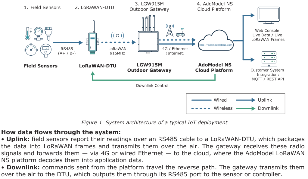
How data flows through the system:
- Uplink: field sensors report their readings over an RS485 cable to a LoRaWAN-DTU, which packages the data into LoRaWAN frames and transmits them over the air. The gateway receives these radio signals and forwards them — via 4G or wired Ethernet — to the cloud, where the AdoModel LoRaWAN NS platform decodes them into application data.
- Downlink: commands sent from the platform travel the reverse path. The gateway transmits them over the air to the DTU, which outputs them through its RS485 port to the sensor or controller.
The role of each component:
| Component | Role in the System |
|---|---|
| Field Sensor | Measures physical quantities (temperature, pressure, flow, etc.) and outputs data through its RS485 interface. |
| LoRaWAN-DTU | The translator between sensors and the wireless world: converts RS485 data to LoRaWAN radio frames, and vice versa. |
| LGW915M Gateway | The relay station between wireless and the Internet: receives LoRaWAN radio frames from end nodes and forwards them to the cloud over 4G or Ethernet. |
| AdoModel LoRaWAN NS Platform | The brain of the network: manages gateways and devices, decodes application data, and provides web console, downlink control, and MQTT / REST API integration. |
The gateway itself never interprets your sensor data — it simply relays LoRaWAN frames. All intelligence (decoding, device management, integrations) lives in the NS platform. This separation is what allows one gateway to serve thousands of heterogeneous devices.
1.3 What This Guide Helps You Accomplish
This guide walks you through everything needed to get a single gateway from the box to a working connection with the AdoModel LoRaWAN NS platform. Follow the chapters in order; by the end you will have:
- unpacked and verified the shipment (Chapter 2);
- installed the antennas, SIM card (optional), and mounting hardware (Chapters 3–4);
- powered the gateway and connected it to the Internet via Ethernet, 4G, or Wi-Fi (Chapter 5);
- opened the gateway web console and verified its platform connection settings (Chapters 6–7);
- seen the gateway appear online on the AdoModel LoRaWAN NS platform (Chapter 8);
- learned what the platform can do for you once the gateway is online (Chapter 9).
If anything does not work as described, turn to Chapter 10 (Troubleshooting).
Connecting end-node devices (e.g., a LoRaWAN-DTU with sensors) to the network is covered in a companion document, the LoRaWAN-DTU Quick Start Guide.
2. Packing List
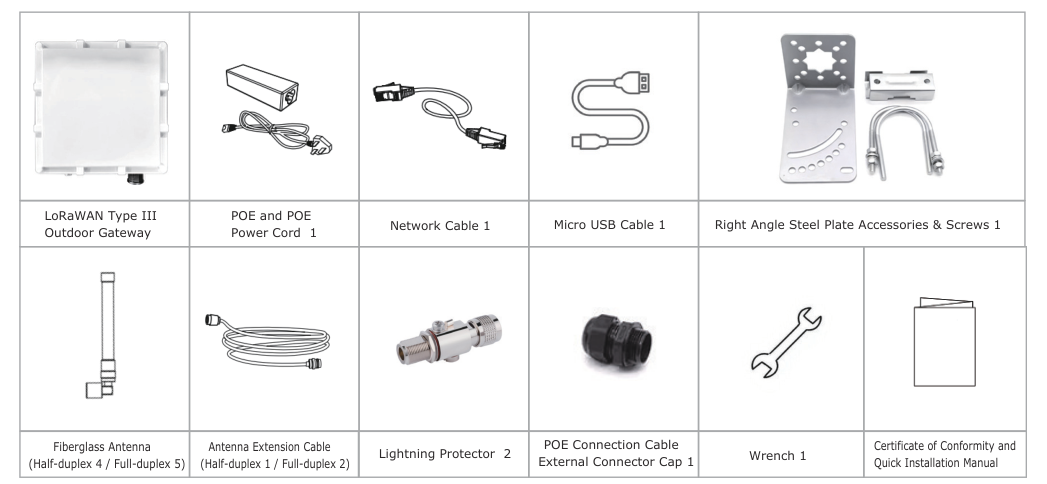
Verify the contents of the package against the illustration below before proceeding with installation. If any item is missing or damaged, contact your sales representative.
3. Interfaces
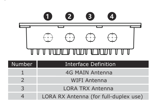
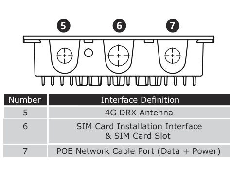
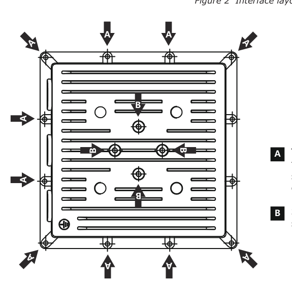
Before installation, familiarize yourself with the gateway’s connectors. Figure 2 shows the interface layout and the definition of each interface.
4. Installation
Install the accessories in the order below. No special tools are required beyond the supplied wrench.
4.1 Installing the SIM Card (4G backhaul only)
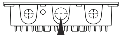
- Twist open the SIM card plug on the side/bottom of the enclosure.
- Insert the SIM card into the slot according to the indicated position, with the metal contacts facing downwards.
- To remove the card later, press and slide the clip on the right side of the SIM card slot.
4.2 Installing the Antennas
Install the corresponding antennas according to the hardware layout (Figure 2):
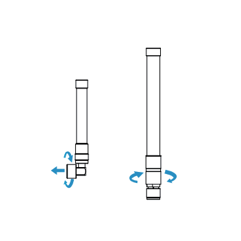
- 4G MAIN / 4G DRX / Wi-Fi antennas: screw the antenna into the interface and try to point it upwards.
- LoRa antennas (LORA TRX and, on full-duplex models, LORA RX): if a long fiberglass antenna is used, an N-type male to N-type male feeder (extension) cable is required for connection, as shown in the installation diagram. A long LoRa antenna requires a patch cable for connection.
4.3 Connecting the Ethernet Cable
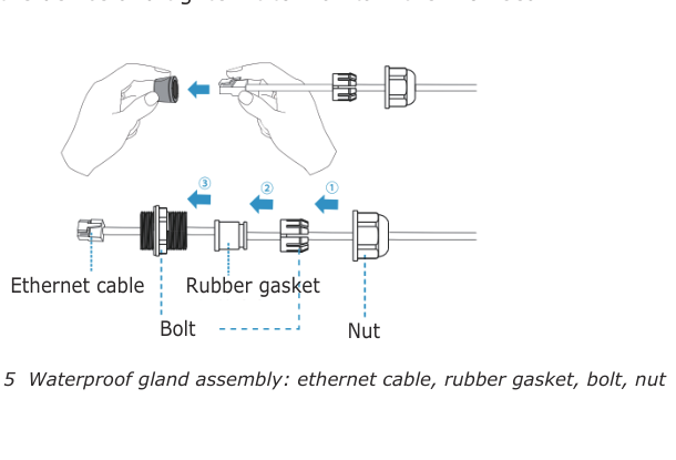
- Pass the network cable through the waterproof gland (rubber gasket, bolt, and nut).
- Connect the cable to the gateway’s POE network port.
- Screw the gland onto the device and tighten it to maintain the IP67 seal.
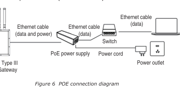
4.4 POE Wiring
Connect the ethernet cables and power cord to the corresponding ports on the POE power supply according to the port labels:
- PoE port → ethernet cable (data + power) → gateway POE network port
- LAN port → ethernet cable (data only) → switch / router
- Power input → power cord → power outlet (AC 100–240 V)
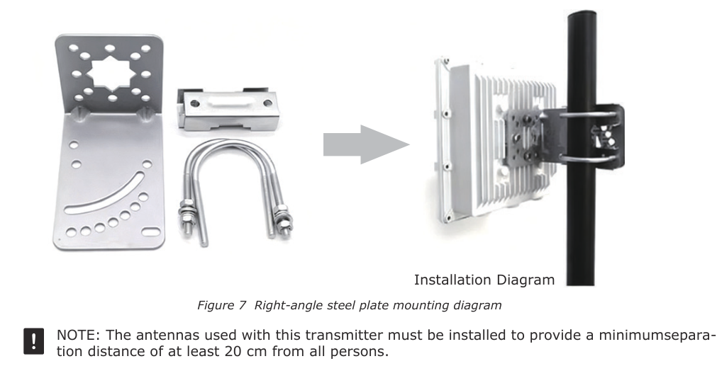
4.5 Mounting with the Right-Angle Steel Plate
The supplied right-angle steel plate allows the gateway to be fixed to a wall, pole bracket, or other structure. Fix the plate to the gateway’s structural mounting screw holes (4 screws), then secure the assembly at the installation location using appropriate hardware for the surface.
5. Power On & Network Backhaul
This chapter powers the gateway up and connects it to the Internet. The gateway supports three backhaul options:
| Backhaul | Best for | What to do |
|---|---|---|
| Ethernet (recommended) | Fixed installations with a wired network available | Just complete the POE wiring of Section 4.4 — the gateway obtains an IP address automatically (DHCP). No further configuration is needed. |
| 4G (cellular) | Sites without wired network access | Install the SIM card (Section 4.1) and the 4G antennas (Section 4.2). The modem dials up automatically after power-on. |
| Wi-Fi | Sites with an existing Wi-Fi network | Power on with the Wi-Fi antenna installed, then configure the Wi-Fi connection on the gateway web console (Chapter 6 → Network settings). |
5.1 Powering On
Complete the installation steps of Chapter 4, then:
- Check that both LoRa antennas (LORA TRX and LORA RX on full-duplex models) are connected.
- Connect the gateway to the POE power supply (data + power cable), or verify it is already connected.
- Plug the POE power supply into an AC 100–240 V / 50–60 Hz outlet.
5.2 Post Power-On Checks
- The POE power supply indicator is lit.
- The ethernet cable is firmly seated at both the gateway and the POE power supply.
If troubleshooting is ever needed later, the network indicator blinks when the ethernet link is active.
Once powered and connected to the Internet, the gateway automatically starts sending data to the NS platform. In a good network environment the gateway comes online within 1–3 minutes of power-on (up to ~5 minutes). You will verify this on the platform in Chapter 8, after checking the web console settings in Chapters 6–7.
6. Accessing the Gateway Web Console
The gateway is managed through a built-in web console. There are four ways to reach it:
- Option 1 — USB connection: connect directly to the gateway with the supplied Micro USB cable. Works even before the gateway has any network set up.
- Option 2 — Ethernet via your LAN: connect the gateway to your router or switch and look up its IP address with the supplied LoraGW_IPScan tool.
- Option 3 — Direct Ethernet connection (server mode): plug your computer straight into the gateway’s ethernet port; the gateway assigns an IP address to the computer automatically. No network infrastructure or extra tools needed.
- Option 4 — Remote access via the CMP platform: if the gateway is already online, open its web console remotely through the AdoModel IoT Management Platform (CMP) without going on site.
6.1 Option 1: USB Connection
- Locate the Micro USB port below the SIM card holder on the gateway.
- Use the supplied Micro USB cable to connect the gateway to your computer.
- Open a web browser on the computer and enter the default gateway address:
http://192.168.0.100:8088
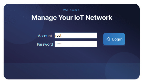
The web console login page appears (Figure 8). Default Username/Password: root / admin
6.2 Option 2: Ethernet via Your LAN
Use this method when the gateway is (or will be) installed on a local area network with a router or switch — the typical case for Ethernet-backhaul installations.
- Connect the gateway’s ethernet port to an available LAN port (for outdoor gateways: the ethernet/LAN port of the POE adapter), and the POE uplink to your router or switch.
- Make sure the network has DHCP enabled — the gateway obtains its IP address automatically by default.
- Power on the gateway and wait about 40 seconds for it to finish booting and obtain an IP address.
- On a computer connected to the same LAN, open the supplied LoraGW_IPScan tool to find the gateway’s IP address.
- Enter the IP address followed by port 8088 in a browser — for example, if LoraGW_IPScan reports 172.16.10.107, enter:
http://172.16.10.107:8088
6.3 Option 3: Direct Ethernet Connection (Server Mode)
Use this method when you want to configure the gateway with a single computer and no router, switch, or search tool.
- Using the supplied ethernet cable, connect your computer’s network port directly to the gateway’s ethernet port (for outdoor gateways: the ethernet port of the POE adapter).
- Power on the gateway and wait about 3 minutes. The gateway automatically assigns an IP address to your computer.
- Once the computer has obtained a valid IP address, open a browser and enter the server-mode address:
http://192.168.100.105:8088
6.4 Option 4: Remote Access via the CMP Platform
- Log in to the AdoModel IoT Management Platform (CMP) (account provided by your account manager).
- Click “Device Management” to expand the menu, then click “Group”.
- Enter the gateway ID (IMEI) in the search box and click “Search”.
- Click “View” on the found device.
- Under the operation column, click “Remote Configuration” (Figure 9).
- Confirm the device status is “Online”, then click “Enable Remote Connection”. Wait until a dialog confirms success and shows the “Open Configuration Page” and “Close Remote Connection” buttons.
- Click “Open Configuration Page” — the gateway web console login page opens.

7. Connecting to the AdoModel Platform
7.1 Verifying the NS Settings
The gateway is factory-configured for the North American band (US915) and for the AdoModel LoRaWAN NS platform. In most cases you do not need to change anything on this page — just verify that the settings match the table below.
- Open the gateway web console (Chapter 6).
- Go to “LoRaWAN Management” → “Parameter Config”.
- Verify the following values:
| Setting | Expected value (North America) |
|---|---|
| NS server address | adomodelcloud.com |
| Uplink port | 915 |
| Downlink port | 915 |
| Band | US915 (US_902-928) |
| Frequency points | 0–7 |
7.2 Using a Different Network Server
If you operate your own LoRaWAN network server (e.g., ChirpStack or The Things Stack), enter its address and ports on the same page. Frequency-plan customization is beyond the scope of this guide — see the companion Gateway Web Configuration Guide and the LoRaWAN band / custom frequency-point reference.
8. Verifying the Gateway Is Online
8.1 Log In to the NS Platform
- Open http://adomodelcloud.com:4560/ in your browser.
- Log in with the account provided by your account manager.
8.2 Check the Gateway Status
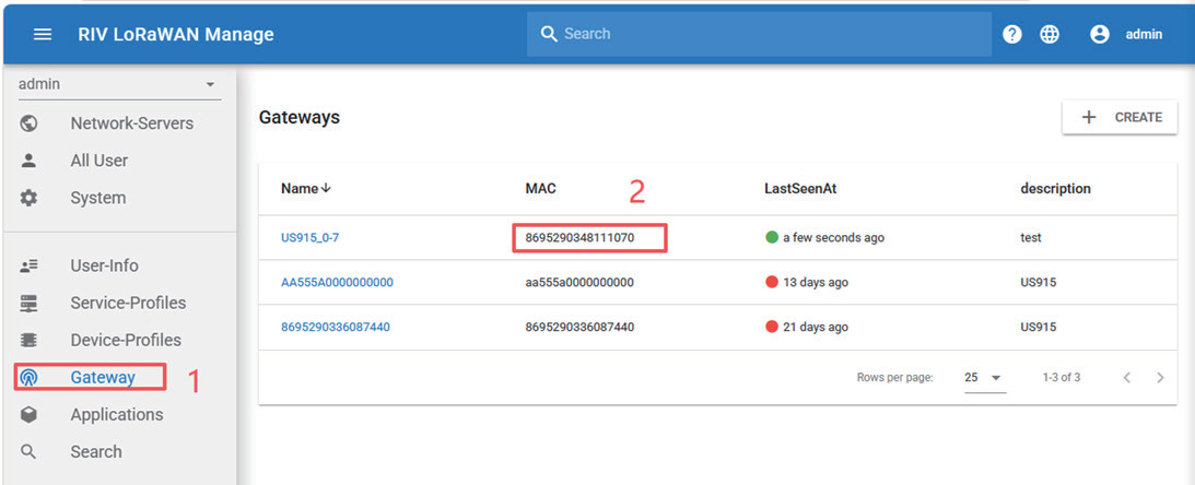
- Click the “Gateway” tab on the left side.
- Enter the gateway MAC ID in the “Search” box and locate your gateway (Figure 10). If it does not exist, click the “CREATE” button in the upper left corner to create it.
- Check the status dot:
- Green dot — the gateway is online and connected to the platform. You are done with this guide’s setup path; continue to Chapter 9 to learn what the platform offers.
- Red dot — the gateway is offline. After power-on (or a new registration), the gateway typically comes online within 1–3 minutes in a good network environment, and within about 5 minutes at most. If it is still offline after 5 minutes, see Chapter 10.
8.3 Alternative Check via CMP
You can also confirm that the gateway has Internet access from the CMP platform: search the gateway ID as described in Section 6.4; an “Online” status means the backhaul link works. If the gateway is online in CMP but offline on the NS platform, re-check the NS settings of Chapter 7.
9. What the Platform Can Do for You
Once your gateway is online, the AdoModel LoRaWAN NS platform is your window into the network. Highlights:
- Applications & device management — organize end-node devices into applications; register devices, manage activation keys (OTAA), and monitor device status.
- Live Data — view decoded application data from your devices in real time.
- Live LoRaWAN Frames — inspect raw LoRaWAN protocol frames (e.g., JoinRequest / JoinAccept) for network debugging.
- Downlink control — send commands to devices from the platform (e.g., through the downlink tool).
- Integration — retrieve your data via standard RESTful APIs and MQTT subscriptions for custom application development.
A quick end-to-end walkthrough — registering the gateway and a LoRaWAN-DTU node, and testing uplink/downlink data — is provided in the companion LoRaWAN-DTU Quick Start Guide. The complete platform documentation is available separately (AdoModel NS Platform User Guide).
10. Troubleshooting
| Symptom | Possible cause | What to do |
|---|---|---|
| Web console page will not open (USB) | Cable not seated; wrong address; browser cache | Re-seat the Micro USB cable; confirm the address http://192.168.0.100:8088; try another browser or clear the cache. |
| Web console page will not open (CMP remote) | Gateway not Online in CMP | Remote configuration only works when the gateway has Internet access. Use a local method (USB 6.1, LAN 6.2, or direct ethernet 6.3) instead. |
| Login fails | Wrong credentials | Use the defaults root / admin. If the password was changed and lost, restore factory settings or contact support. |
| Gateway never comes online on the NS platform | No backhaul link; wrong gateway ID on the platform; NS settings mismatch | 1) Check that the ethernet/4G link works (CMP status, Section 8.3). 2) Compare the gateway ID on the platform with the label on the device. 3) Verify the NS settings (Chapter 7). 4) Power the gateway off for about 15 seconds and power it on again. Note: the network indicator is inside the enclosure. |
| 4G backhaul does not connect | SIM not detected; no data plan; weak signal | Power off, re-insert the SIM (contacts facing down), power on; confirm the SIM has an active data plan; attach both 4G antennas and check signal coverage at the site. |
For further assistance, contact your agent or sales representative, or visit www.adomodeltech.com.
Appendix A: Specifications
Key specifications of the gateway (from the LGW-M-III Product Specification; refer to the full specification sheet for details):
| Item | Specification |
|---|---|
| Processor | ARM Cortex-A7 |
| Storage | NAND + LPDDR2 (4 Gb + 2 Gb) |
| LoRaWAN channels | 8 |
| Frequency band | LoRaWAN US915, LTE FDD B2/4/5/12/17 |
| Receiving sensitivity | -143 dBm |
| Transmission power | Max. 30 dBm |
| LoRaWAN antenna | 2× N-type female connectors, external antenna, 50 Ω |
| LoRaWAN protocol | V1.0.4 and V1.0.2, Class A / C |
| Ethernet port | 1× 10/100/1000 Mbps (802.3af PoE) |
| Cellular network | 2× LTE external antennas (main + diversity), 50 Ω |
| SIM port | 1 (Nano SIM) |
| Other interfaces | Micro-B debug interface ×1; Network indicator |
| Power supply | 802.3af standard PoE |
| Power consumption | Avg. 3.4 W; peak 5 W |
| Protection level | IP67; flame-retardant grade V0; aluminum casing |
| Operating temperature | -40 °C to +85 °C |
| Storage temperature | -50 °C to +100 °C |
| Relative humidity | 10%–90% RH, non-condensing |
| EMC protection | Contact discharge 4 kV; air discharge 8 kV |
| Installation | Wall-mounted or pole-mounted |
Appendix B: Default Parameters
| Parameter | Default value |
|---|---|
| Web console address (USB) | http://192.168.0.100:8088 |
| Web console address (direct ethernet, server mode) | http://192.168.100.105:8088 |
| Web console username / password | root / admin |
| Ethernet mode | DHCP (IP lookup via supplied search tool) |
| NS server address | adomodelcloud.com |
| NS uplink / downlink port | 915 / 915 |
| Band / frequency points | US915, points 0–7 |
| NS platform web address | http://adomodelcloud.com:4560/ |
| CMP platform web address | http://adomodelcloud.com/ |
Download PDF Version
Prefer a printable version? Download the complete Quick Start Guide as a PDF.
Download PDF