LoRaWAN-DTU Quick Start Guide
User Guideline (UG) · Classification: Controlled · Rev 1.1 — Configure DTU, Gateway and NS for quick LoRaWAN-DTU deployment.
1. Overview
This document is intended to enable quick implementation of LoRaWAN-DTU usage.
1.1 Purpose
Configure DTU, Gateway and NS to enable quick use of LoRaWAN-DTU.
1.2 Target Audience
This document (user manual) is primarily intended for the following engineers:
- R&D Engineer
- Technical Support Engineer
- Maintenance Engineer
1.3 Scope
The software setup described in this document is based on Windows 10 system.
1.4 References
<Omitted>
2. Hardware List
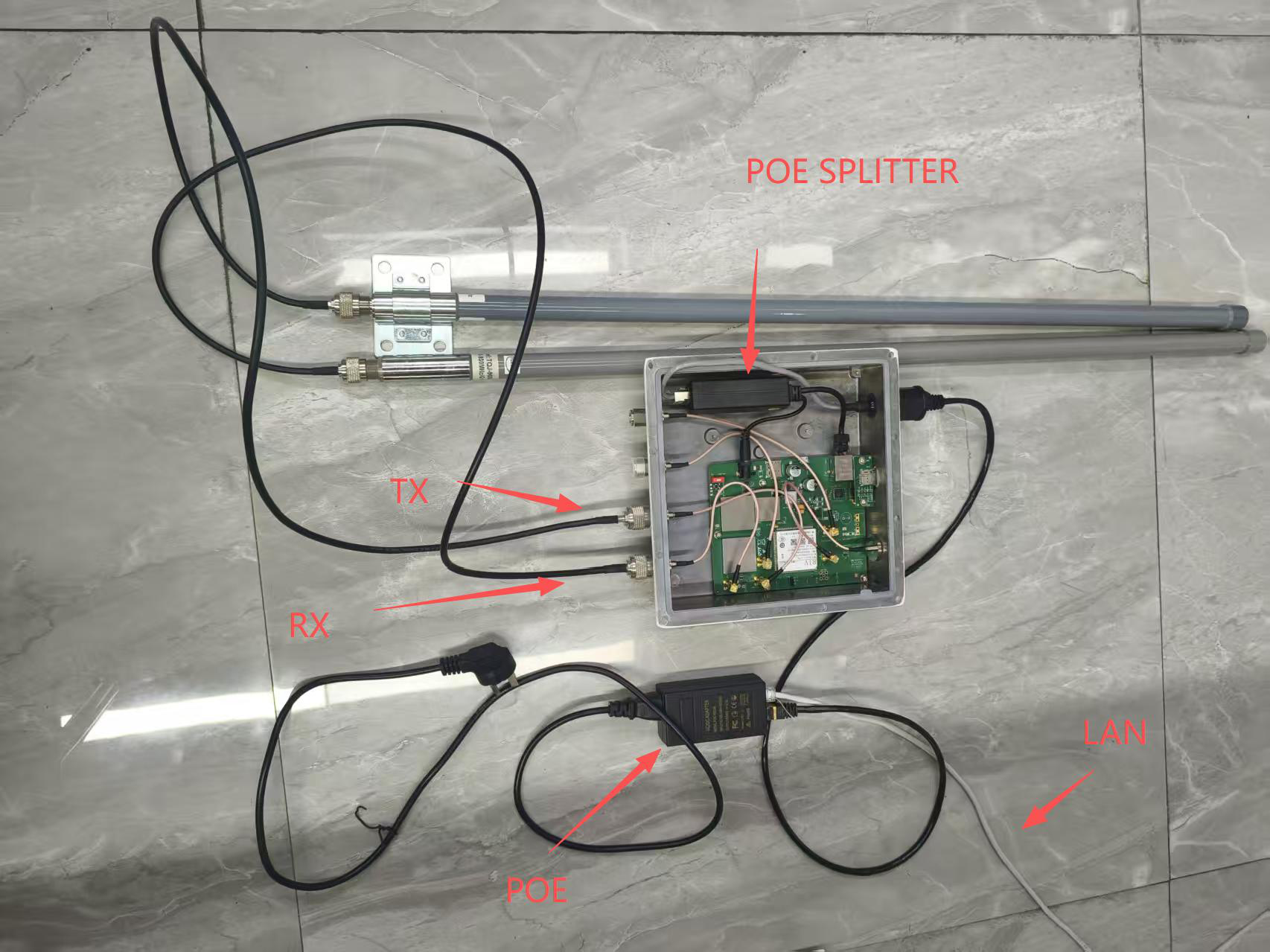
Gateway
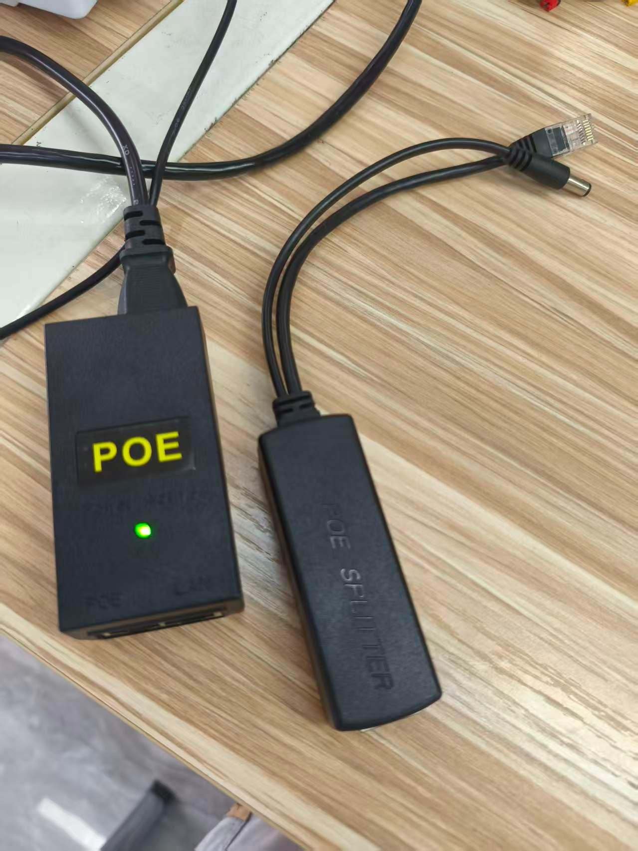
- POE (Input AC 100~240V, Output DC 48V) and POE Splitter (48V Input)
- POE SPLITTER (OUT: 12V 2A; built into the gateway, no manual wiring required)
- 915MHz omnidirectional fiberglass antenna. The antenna should be connected to LoRa_ANT_RX/TX
Overall view:

DTU
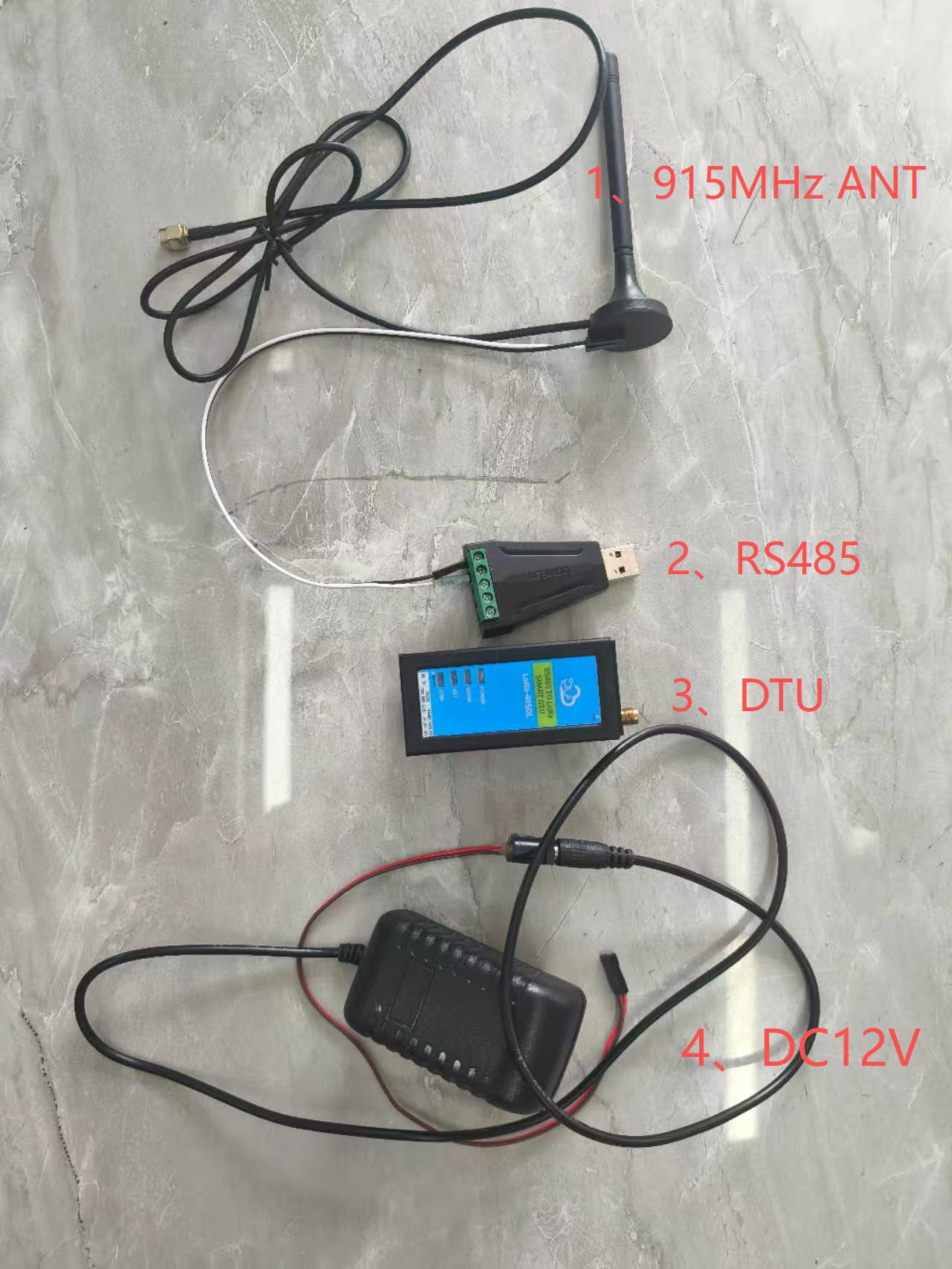
- 915MHz antenna
- RS485 to USB converter (Separate purchase / Optional)
- DTU module
- 12V 1A DC adapter (Separate purchase / Optional; DC 9~12V, 1~2A is acceptable)
3. Gateway
The gateway is pre-configured by default. You only need to log in to the backend for checking if it cannot uplink data to NS.
3.1 Log in to LoRaWAN Gateway
Methods to obtain the gateway IP address:
- Log in to the router admin page and open the DHCP client list.
- Unplug and plug the network cable of the gateway, then refresh the DHCP client list. The IP address that appears again is the gateway IP address.
Gateway Login
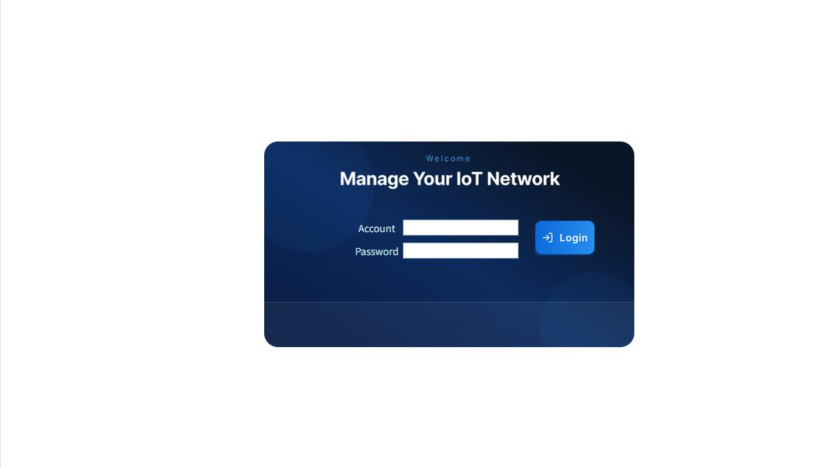
After obtaining the IP address, connect the gateway with a network cable. Use a computer in the same LAN to log in via ip + 8088, e.g.: xx.xx.xx.29:8088
Default username: root
Default password: admin
3.2 Frequency Point and NS Configuration
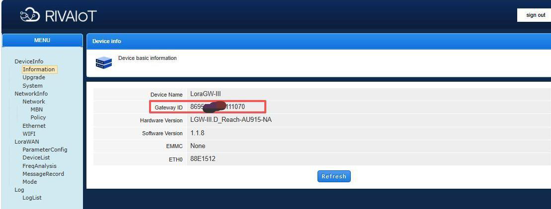
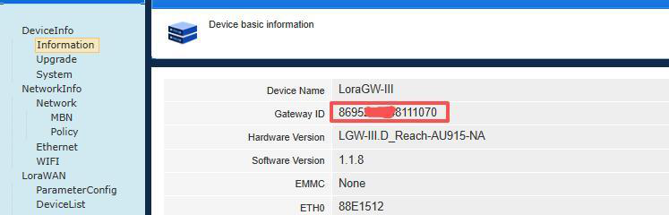
The default page is "Device Information", where you can view the gateway ID and version number. The ID can also be obtained from the label on the gateway.
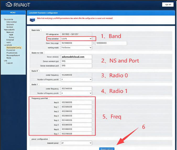
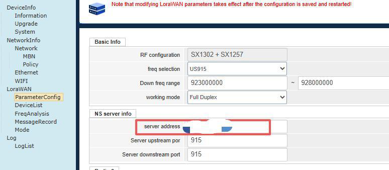
Click "ParameterConfig" on the left to configure frequency points and NS.
Frequency points are pre-configured by default before shipment and do not need modification. Just confirm whether the NS address is correct.
North America NS address: adomodelcloud.com
3.3 Modify Static IP
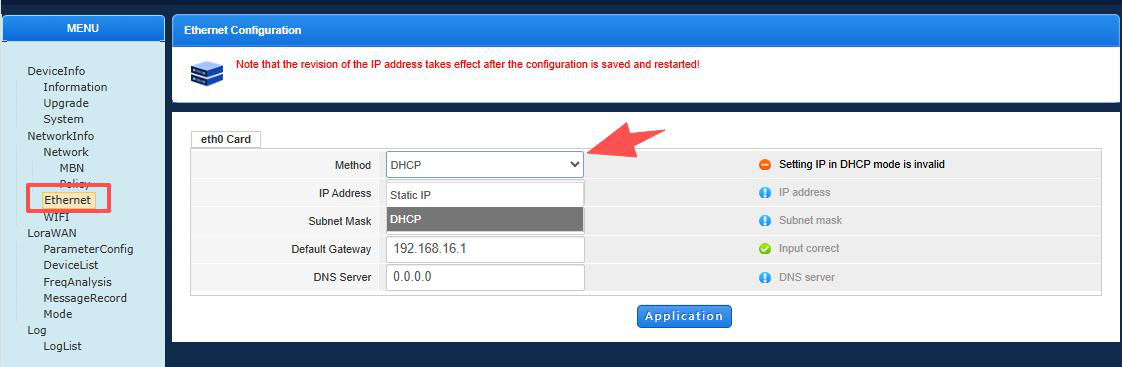
The gateway uses dynamic IP by default, and the IP may change after power reboot. To set a static IP:
- Click "Ethernet" on the right.
- Select "Static IP" in the "Method" field.
- Click Apply below.
- After successful application, wait 10 seconds and reboot the gateway. The static IP will take effect.
4. LoRaWAN NS
4.1 Login
North America LoRaWAN NS website: http://adomodelcloud.com:4560/
Account and password shall be provided by the sales representative.
4.2 Add Gateway
First ensure that the NS address configured on the gateway is consistent.
4.2.1 If Gateway Already Exists
Check if the frequency band is correct.
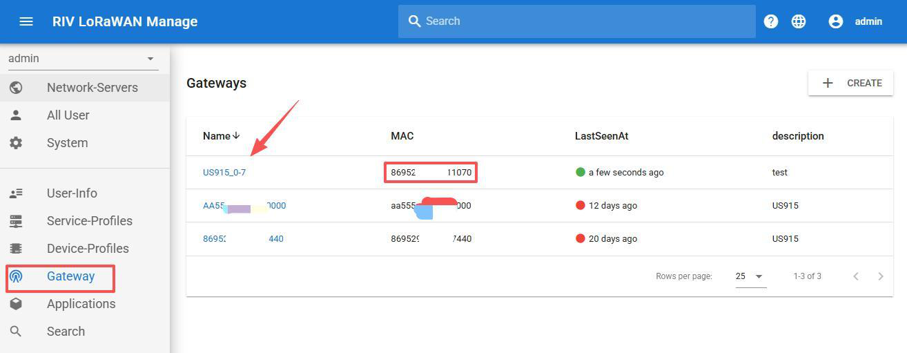
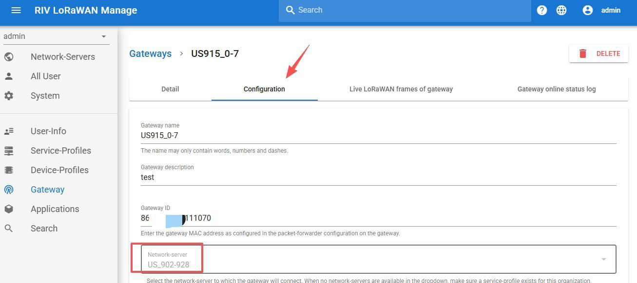
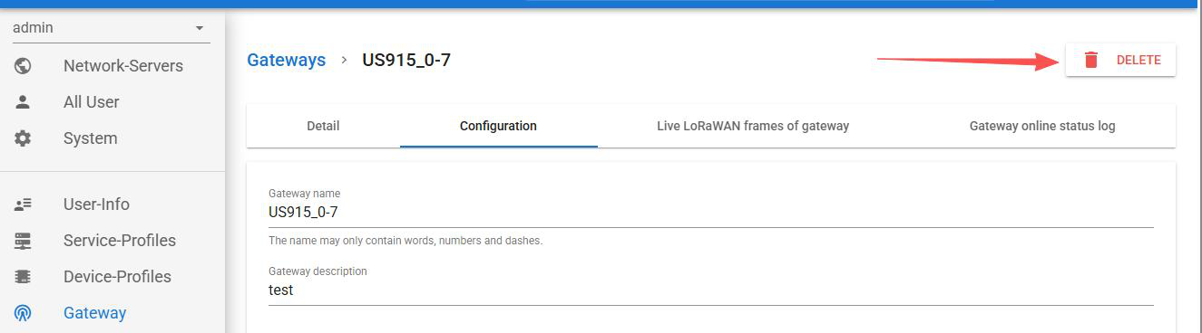
If the frequency band is correct, no modification is needed. If incorrect, click Delete Gateway on the left and add again.
4.2.2 Create New Gateway
Click "Gateway" on the left, then "New Gateway".
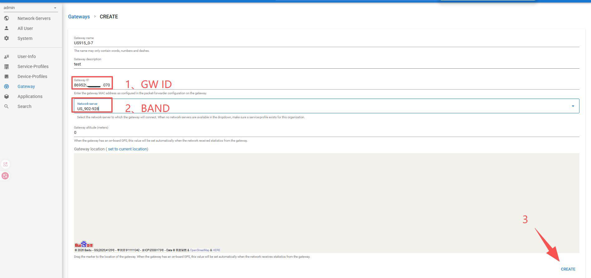
Gateway name and description can be filled arbitrarily, height defaults to 0.
-
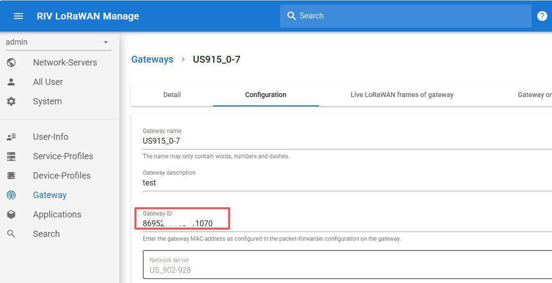
Gateway ID:
- Can be obtained by logging into the gateway
- Can be obtained from the label value on the gateway (ID is 16 digits, if the label only has 15 digits, add 0 at the end).
-
Network Server: Select the same frequency band as configured on the gateway. The previous gateway is configured with US915 0-7, so select US_902-928 here (note: US_902-928 is for 0-7 channels, while US_902-928-2 is for 8-15 channels).
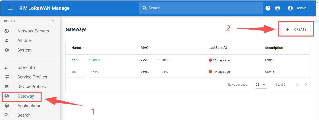
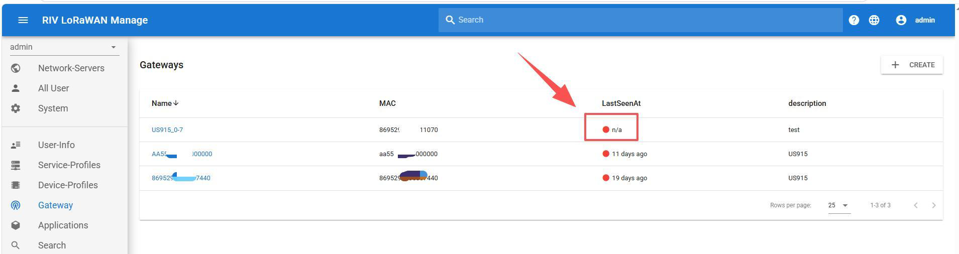
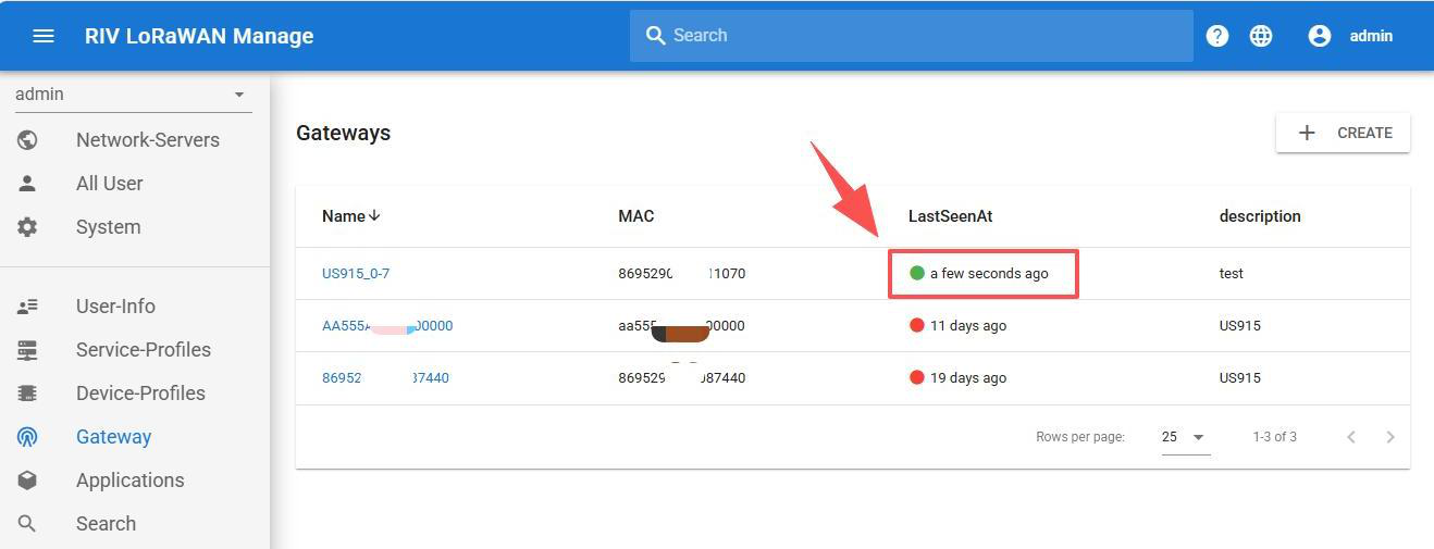
The newly created gateway will display a red dot, indicating offline status.
Wait for about 5 minutes and refresh the page. It turns green when online successfully.
4.3 Create New Application
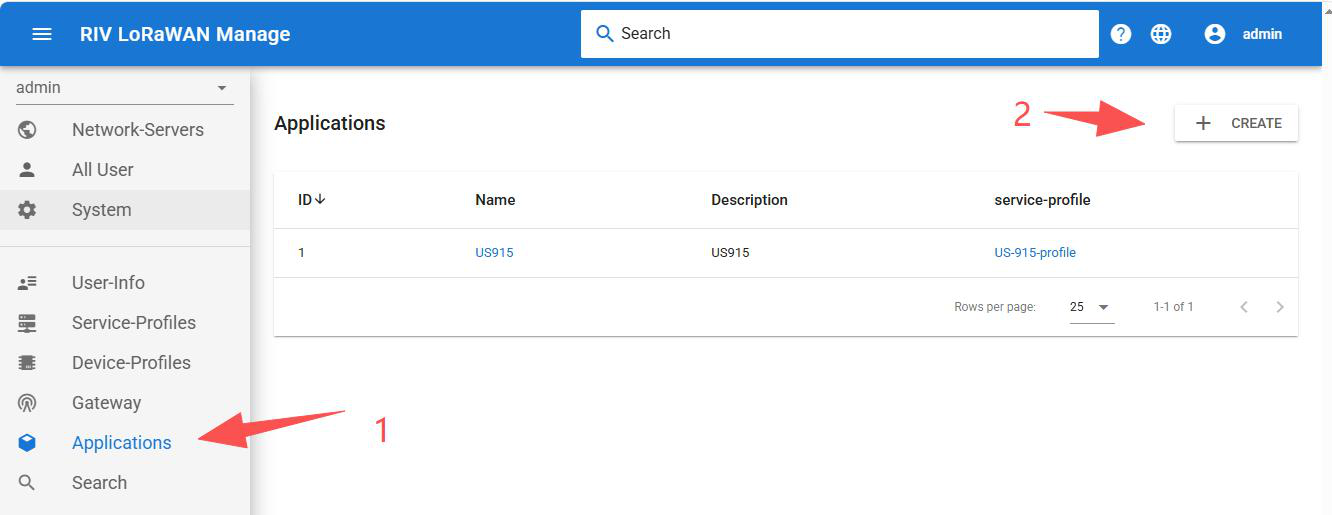
Click "Application" on the right, then "New Application".
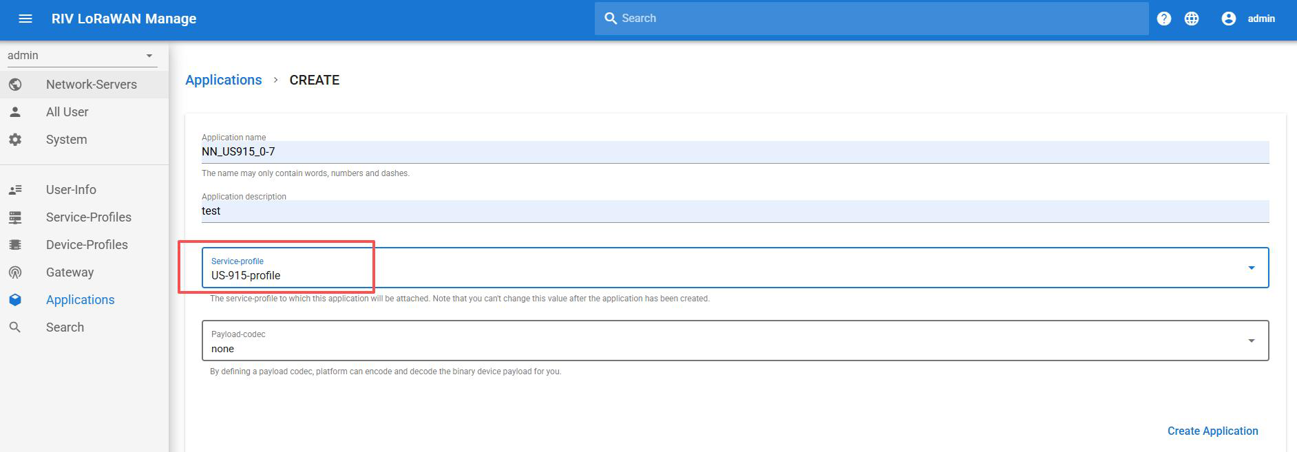
"Application Name" and "Application Description" can be filled arbitrarily. Select "None" for "Payload Data Encoder".
"Network Service Configuration" selects US-915-profile.
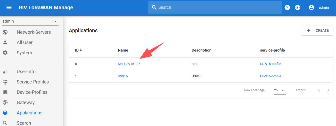
Click the application name to enter the application.
4.4 Add Device
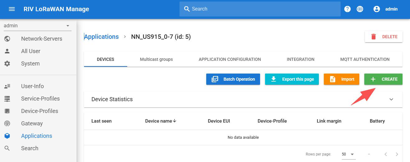
Devices need to be added within the application.
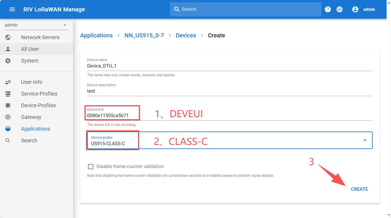
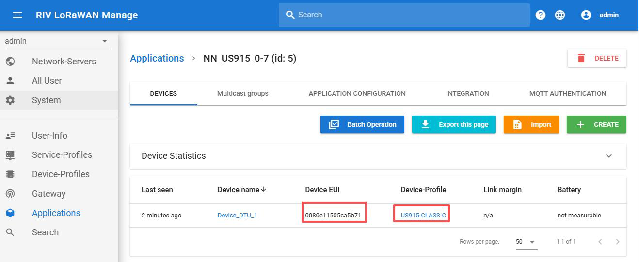
DEVEUI (IMEI): Can be obtained from the label on the side of DTU, or read using the host computer software.
CLASS: DTU uses classC mode by default.
Click Create.
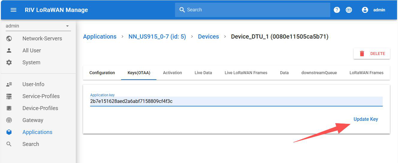
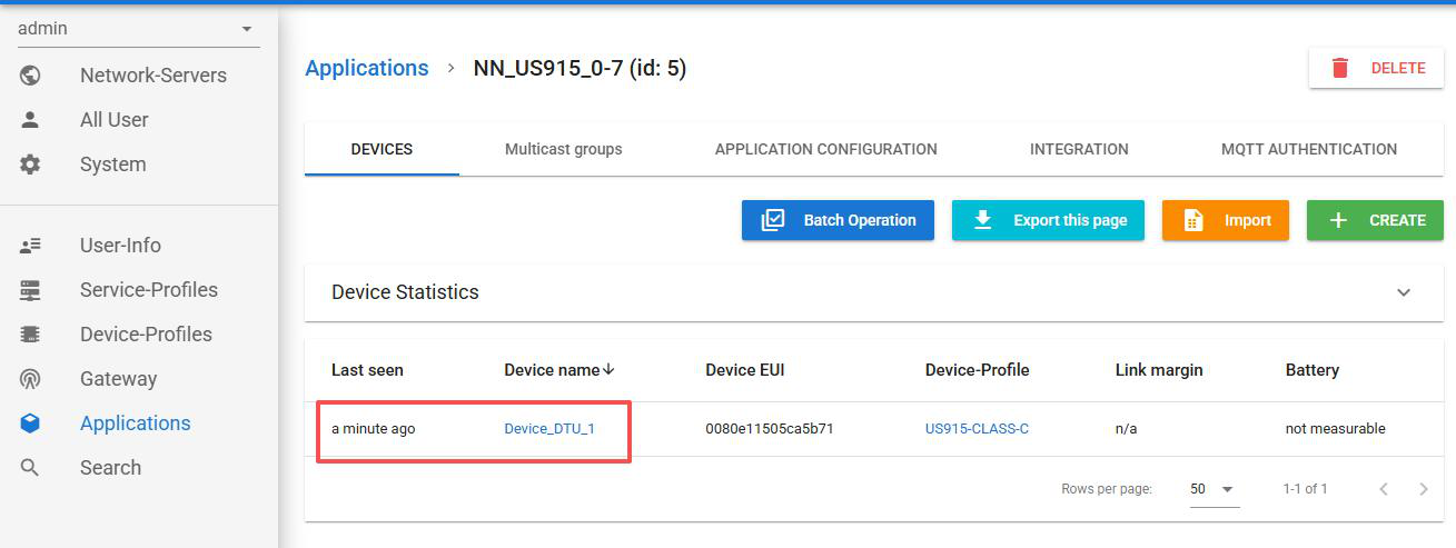
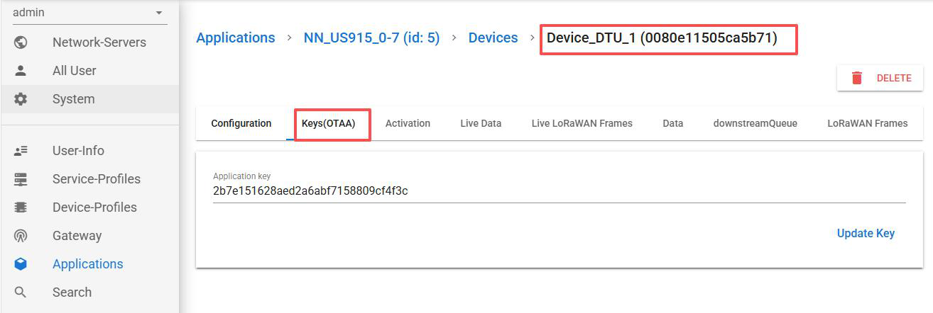
After clicking Create Device, you will be redirected to the APPKEY page. APPKEY can also be obtained from the label on the side of DTU or read via the host computer software. Click Update Key, and the device addition is completed.
Re-enter the created application, and the application you just created will be displayed.
5. DTU
5.1 Hardware Connection
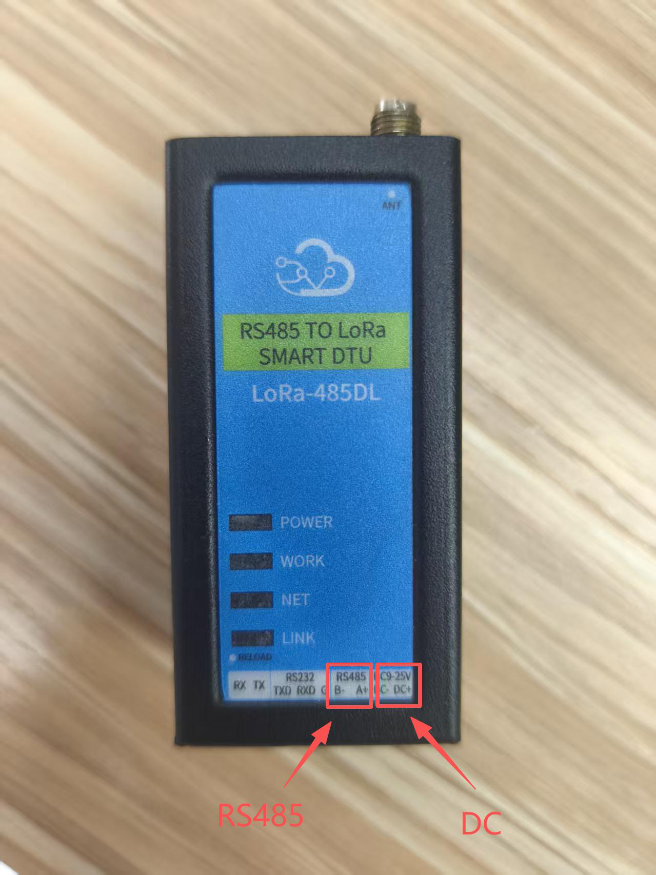
The DTU connects field sensors to the LoRaWAN network. The RS485-to-USB connection (Scenario A) is for quick start and configuration — the DTU must be configured this way before a sensor can be used. The sensor is connected to the RS485 port (Scenario B).
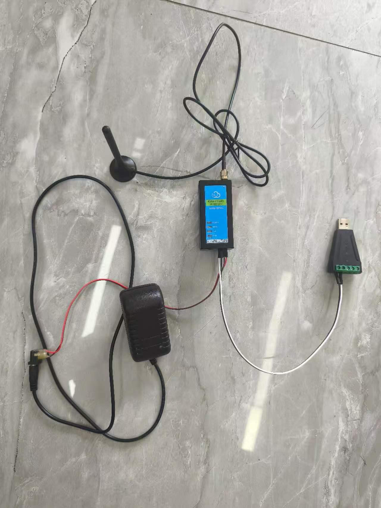
Scenario A — RS485-to-USB connection (quick start and configuration):
- Connect the 12V 1A adapter to the DC port of DTU
- Connect RS485 to USB converter to the RS485 port of DTU
- Connect the rubber antenna to the antenna port
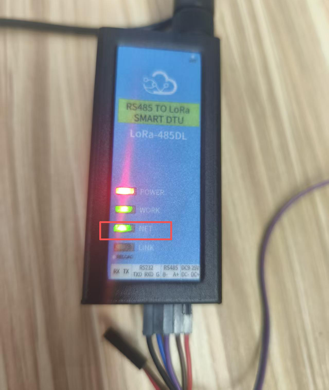
After normal power-on: POWER light is always on, WORK light flashes every 1 second
Scenario B — connecting a real sensor:
Connect the sensor to the DTU over RS485: sensor A+ / B− to the DTU's A+ / B− terminals (observe the polarity; if the sensor uses a modular RS485 connector, refer to its pinout). Power the sensor as required by its datasheet — some sensors share the DTU's 12 V supply. The antenna and DC power connections are the same as in Scenario A.
Wiring reference table (Scenario B):
| Sensor side | DTU side | Note |
|---|---|---|
| RS485 A+ | A+ | Data positive line |
| RS485 B− | B− | Data negative line |
| Power + (if required) | External 12 V supply | Per sensor datasheet |
| GND | GND | Common ground recommended for stable RS485 communication |
5.2 Host Computer Configuration
5.2.1 Open Serial Port on Host Computer
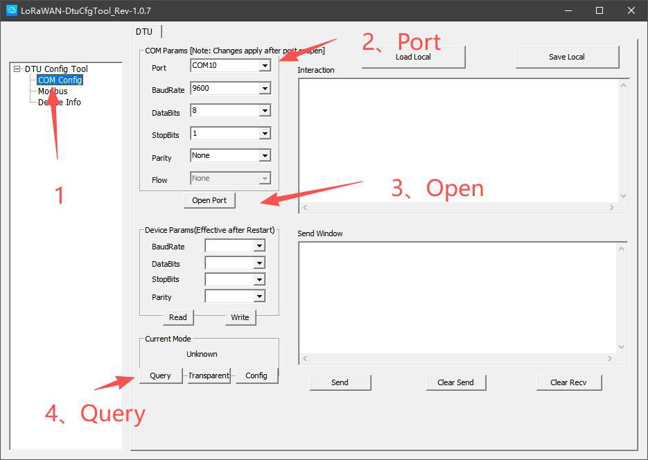
- Open the host computer software, the default page is "COM Config"
- Click the Port drop-down box to select the RS485 port
- Use default values for other parameters: 9600 8N1.
- Click Open Serial Port
- Click Query. If "Transparent" or "Config" is displayed above, it indicates successful connection to DTU
5.2.2 Configure LoRaWAN Parameters
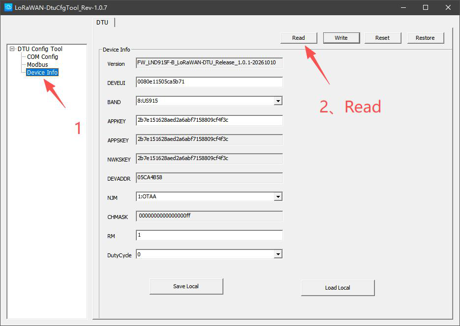
- Click "Device Info" on the left
- Click "Read" and wait for about 20 seconds to get all parameters
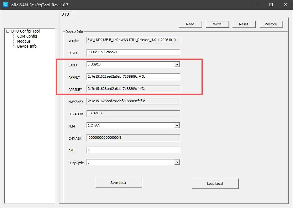
Modify parameters. If the parameters are already consistent with NS, no modification is needed. Generally only modify: APPKEY, leave other parameters unchanged.
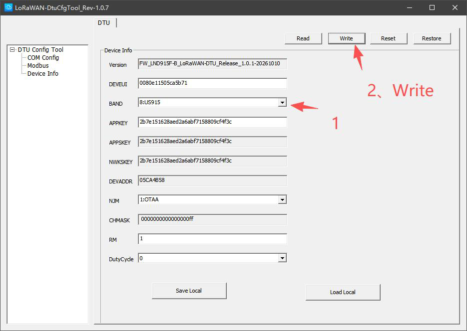
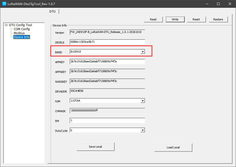
Confirm that BAND is US915 (factory default for North America), then click Write.
After Write, DTU parameters will be automatically re-read. If the read parameter is US915 as shown in the figure, it indicates successful writing.
5.2.3 Configure Modbus Parameters
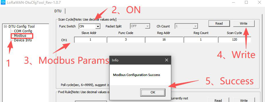
Modbus polling is optional — configure it only when the sensor must be polled by the DTU over Modbus. Modbus is disabled by default and must be enabled manually.
- Switch to the Modbus page.
- Turn the switch ON.
- Enter the Modbus parameters. Scan Cycle is the polling period — minimum 6 seconds (for testing); use more than 120 seconds in normal operation.
- Click Write.
- A pop-up message confirms that the write was successful.
5.3 DTU Function Verification
After configuring parameters with the host computer software, close the software and reboot the DTU.
5.3.1 Automatic Network Access
First ensure that the gateway is online on NS, and NS has created an application and added the device. Use the host computer software to read LoRaWAN parameters to ensure consistency with NS's DEVEUI, APPKEY, and BAND.
DTU will automatically access the network after reboot.
The NET light will be on when network access is successful.
Click the device in the NS application.

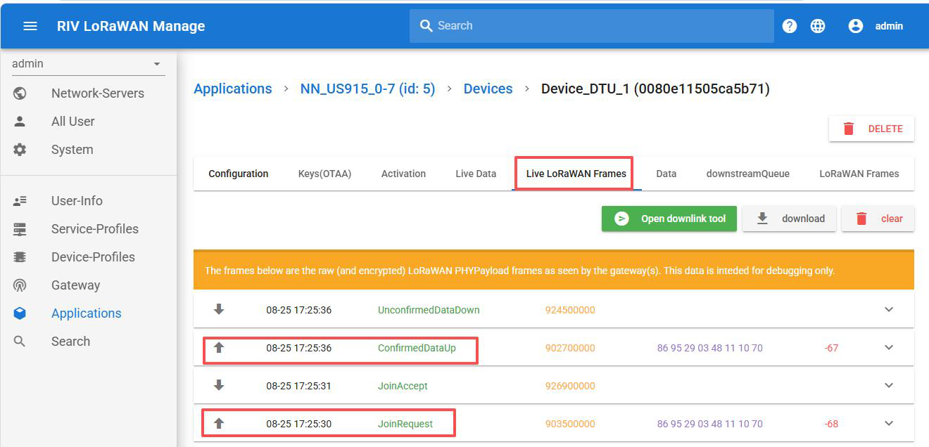
Click "Live LoRaWAN Frame" at the top to view network access requests, responses and data uplink. (An empty packet will be automatically uplinked after network access)
5.3.2 Data Transparent Uplink
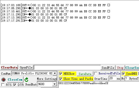
After DTU successfully accesses the network, use a serial port tool to send hex directly through the RS485 port.
Example: 00112233445566778899aabbccddeeff
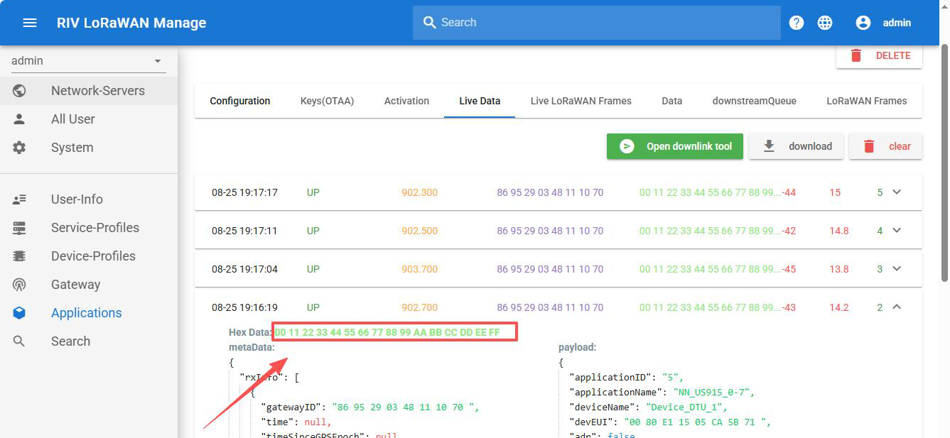
Open "Live Data" of the NS device to check that the hex received by RS485 has been completely uplinked to NS.
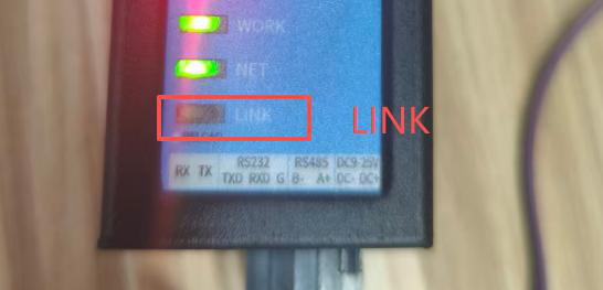
NS will respond after uplink, and the LINK light will flash when DTU receives the response.
5.3.3 Data Downlink
Data can be directly downlinked from NS after DTU accesses the network.
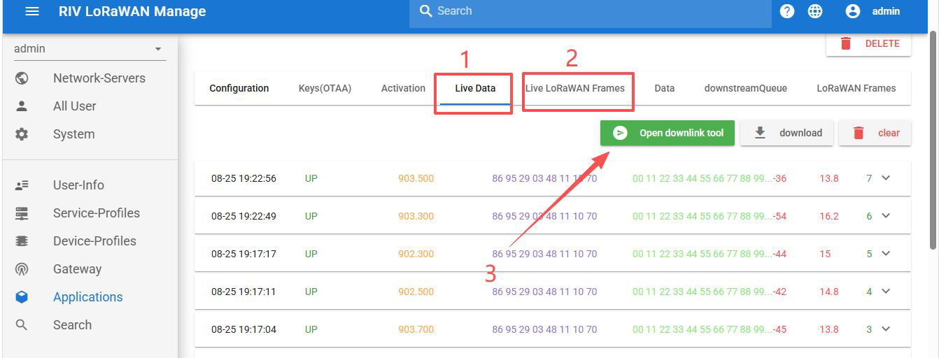
When clicking "Live Data" or "Live LoRaWAN Frames" above the device, there will be a green "Open downlink tool" button, click to open it.
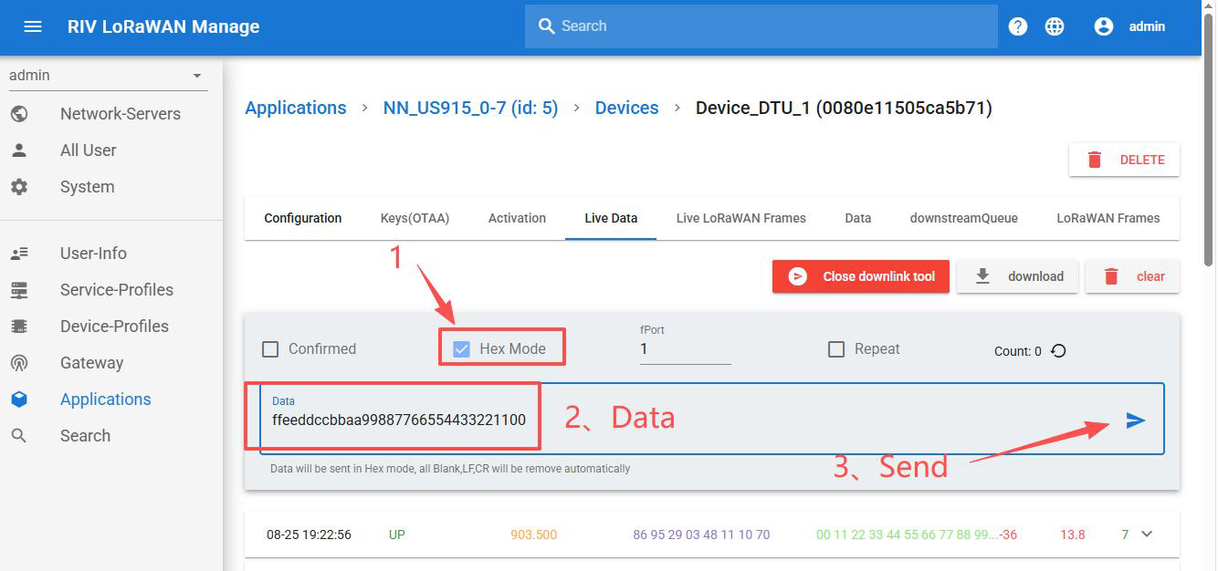
- Check Hex mode
- Fill in data, e.g.:
ffeeddccbbaa99887766554433221100 - Click Send
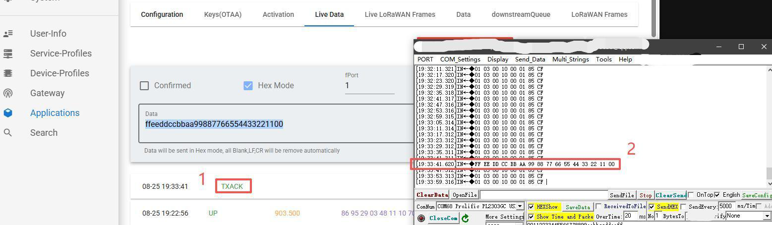
After sending, NS will display TXACK. The LINK light will also flash when DTU receives the downlink data, and the RS485 port will output the downlink HEX content at the same time.
6. Troubleshooting
6.1 Gateway Cannot Go Online
- Verify that the gateway ID and NS address are correct
- Check if the gateway ID on NS matches the actual gateway ID
6.2 DTU Cannot Access Network
Compare DEVEUI, BAND, and APPKEY read from the host computer with those filled in NS to ensure consistency.
NS device DEVEUI and BAND:
NS device APPKEY:
Also ensure that the gateway is configured with the same BAND.
Download the Full Guide
Download the original quick start document (DOC) or the rendered PDF version (Rev 1.1).
Download Source (DOC)Download PDF version (.pdf)