DLA80-485DA Operation Manual
4G LTE CAT4 DTU Module — Configuration & Operation Manual (V1.5, 2026-10-12)
Revision History
| Date | Ver | Author | Change Description |
|---|---|---|---|
| 2025-03-08 | 1.0 | Panshy | Edit Operation Manual. |
| 2025-09-30 | 1.1 | Panshy | Added subcontracting and visualization plugin features. |
| 2026-07-15 | 1.2 | Panshy | Added QoS level and Clean Session features in MQTT mode. |
| 2026-09-15 | V1.3 | Zhwj | Merged Quick Start Guide content: FAQ chapter, AT command appendix, Modbus function code appendix, heartbeat interval rules, local RS232/RS485 switching steps. Filled empty sections 6.3.2/6.4.2/7.1.3/8.2.2. Unified terminology (AT+ADOCFG prefix, ABCD byte order, platform address http://adomodelcloud.com/). Draft questions TBD-1..12 resolved per project decisions 2026-09-15: polling cycle unit = 1 second; LED table per V1.2; MQTT QoS/Clean Session parameters included; Appendix A expanded; Appendix C specifications added. Final spell-check pass by R&D pending. |
| 2026-09-29 | V1.4 | ZHWJ | Restored local RS232/RS485 AT switching table and heartbeat interval rules; added QoS Level / Clean Session to MQTT PC configuration; corrected spelling and punctuation. |
| 2026-10-12 | V1.5 | ZHWJ | Final release. |
1. Introduction
1.1 Purpose
This document introduces the configuration and operational procedures of the DLA80-485DA DTU module (4G LTE CAT4).
1.2 Target Audience
This document is primarily intended for the following personnel:
- Purchasing customers
- Technical support engineers
- System integrators configuring Modbus devices
1.3 Scope
Covers wiring, LED diagnostics, parameter configuration (local PC tool and cloud platform), serial port setup, Modbus polling/parsing, business heartbeat, working modes (TCP/UDP/MQTT), application cases, and troubleshooting for the DLA80-485DA.
1.4 References
- DLA80-485DA hardware specification (see Appendix C)
- AdoModel Cloud platform online documentation (device access chapter), http://adomodelcloud.com/
1.5 Glossary
| Term | Description |
|---|---|
| DTU | Data Transfer Unit. A wireless terminal that converts serial data to IP data (and vice versa) over cellular networks. |
| DCT | The AdoModel PC configuration program used to read and modify DTU parameters. |
| APN | Access Point Name — carrier setting for cellular data dial-up. |
| Modbus | Serial communication Protocol used by the slave devices (sensors, meters, PLCs). |
| Transparent transmission | Data passes through the DTU unmodified between serial port and network. |
| BHU | Business Heartbeat — registration/heartbeat/data packet reporting functions. |
2. DTU Introduction
2.1 Pin Definition
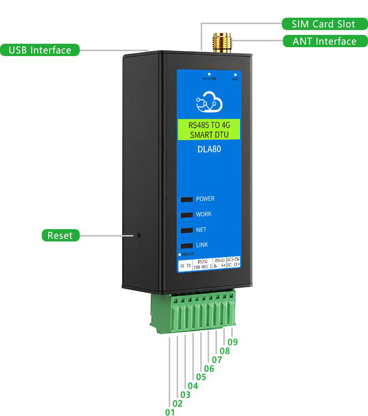
| Pin | Name | Description |
|---|---|---|
| 01 | RX | DEBUG-RX (debug port, not used in daily operation) |
| 02 | TX | DEBUG-TX (debug port, not used in daily operation) |
| 03 | TXD | RS232 TX — connect to RXD of the RS232 device |
| 04 | RXD | RS232 RX — connect to TXD of the RS232 device |
| 05 | GND | Power ground / signal ground |
| 06 | B- | RS485 B- |
| 07 | A+ | RS485 A+ |
| 08 | DC- | Negative power supply |
| 09 | DC+ | Positive power supply, DC 9-25 V (12 V nominal) |
2.2 Equipment Wiring
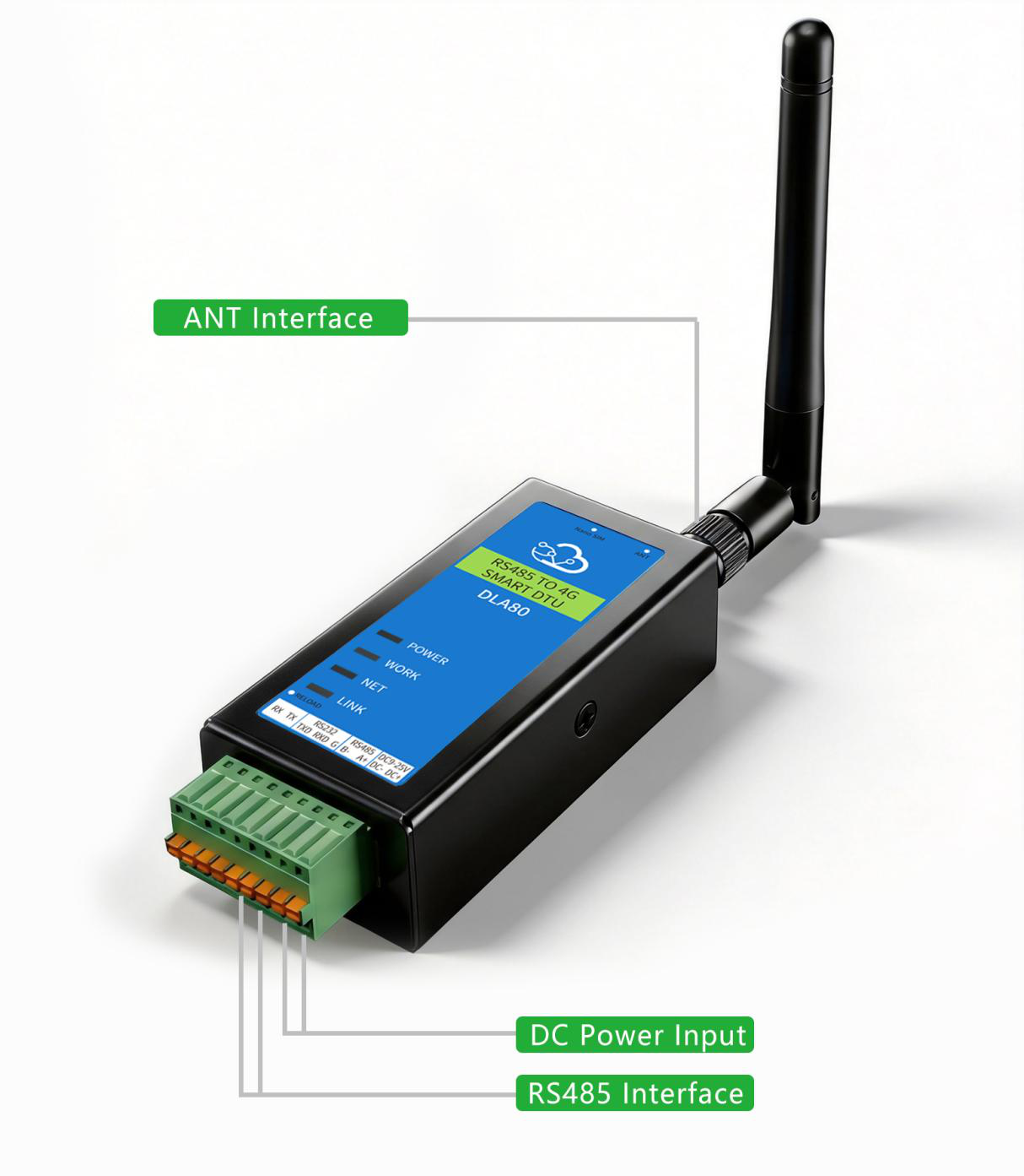
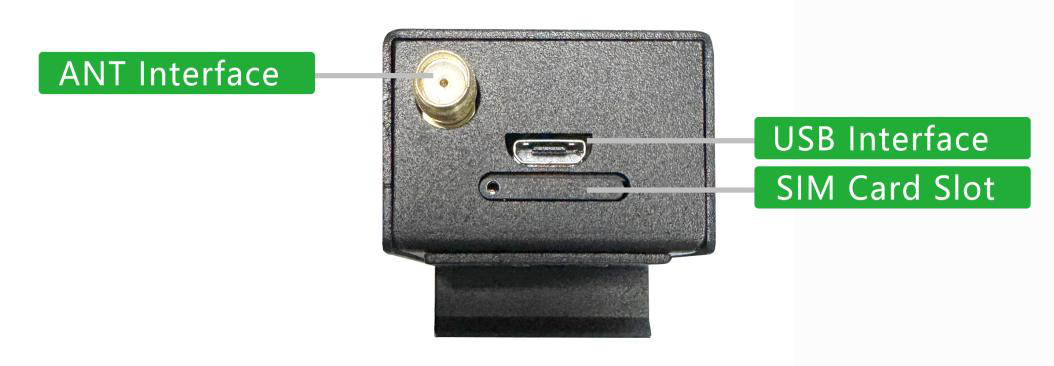
- Step 1 — Attach the LTE antenna to the ANT interface (hand-tight). Do not power on without the antenna.
- Step 2 — Insert 4G SIM card into the slot on the top of the DTU (power off while inserting). SIM requirements: see Appendix C.
- Step 3 — Connect a 12 V DC power supply (range 9-25 V) to DC+/DC- according to the pin definition.
- Step 4 — Connect the RS232 configuration port and/or the RS485 pass-through port as required (see Section 7). Confirm the active data interface before wiring.
- Step 5 — Power on and check the LED indicators (Section 2.3).
2.3 Indicator Light Status
From top to bottom, the indicators are: POWER, WORK, NET, and LINK. Healthy power-up sequence: POWER steady on → WORK slow blink → NET steady on → LINK steady on.
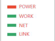
| Indicator | Function | Status | Device State | What to do |
|---|---|---|---|---|
| POWER | Power LED | Off | No power | Check DC+/DC- wiring and supply voltage (9-25 V) |
| On | Powered on | — | ||
| WORK | Work indicator | Off / steady on | Abnormal operation | Short-press reset or power-cycle |
| Slow blink | Normal operation | — | ||
| Fast blink | Data transmission in progress | — | ||
| NET | Network indicator | Slow blink | Not registered on 4G | Check SIM card, antenna, APN, carrier bands |
| Fast blink | Registration / connection failed | Re-seat SIM; verify carrier compatibility; wait 60 s | ||
| On | Connected to 4G network | — | ||
| LINK | Server link LED | Off | No platform connection configured | Configure working mode (Section 6) |
| Slow blink | Not connected to platform | Check network and server settings | ||
| Fast blink | Connection failed | Restart device; check mode config, address/port, product key | ||
| On | Connected to server | — |
2.4 Button Functions
A reset button is located on the side of the device (Section 2.1). Use the supplied SIM ejector pin to operate it.
2.4.1 Short press to restart the device
Short press for 1 to 5 seconds to restart the device; the effect takes place after you release the button.
2.4.2 Long press to restore factory settings
Press and hold for more than 5 seconds to restore factory settings (serial port returns to RS485, 9600-8-N-1); the change takes effect after you release the button.
3. DTU Parameter Configuration
The DTU can be configured in two ways. Both reach the same parameters; choose one path and stay with it:
- Local configuration — PC configuration tool (DCT) via RS232 / USB
- Device Management Platform — remote configuration once the device is online
3.1 Local Configuration
Connect the device to a computer via the RS232 port using three screw-type terminal blocks and a standard USB-to-RS232 conversion cable.
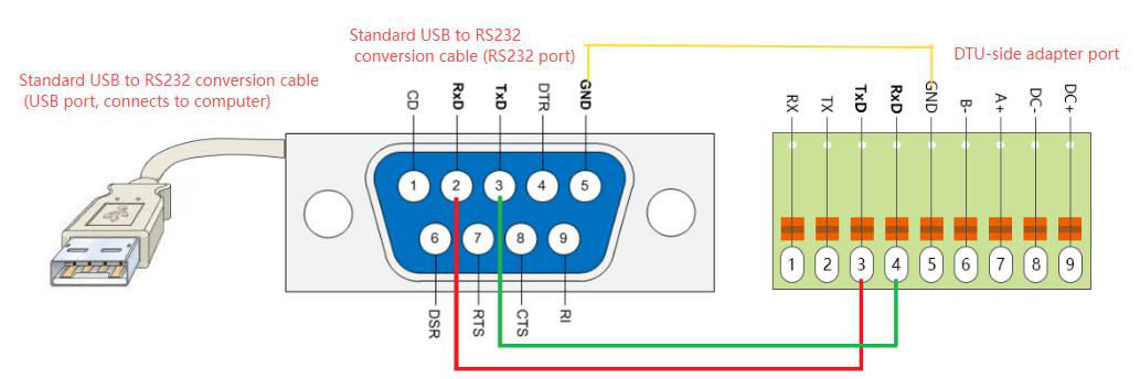
You can obtain the configuration tool installer (AdoModel_DtuCfgTool-x.x.x.exe) from our support team.
Power the DTU via the top USB port or from external DC power; connect the ground wire.
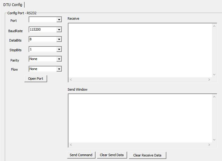
- Open the configuration tool and select the serial port. Default serial parameters:
115200-8-N-1. - Click "Open Port". If opening fails, the port may be occupied by another program.
- Verification: enter
AT+ADOCFG=GET|VERSIONin the send window and click Send. The returned firmware version confirms the link works.
3.2 Equipment Management Platform
3.2.1 Account Registration
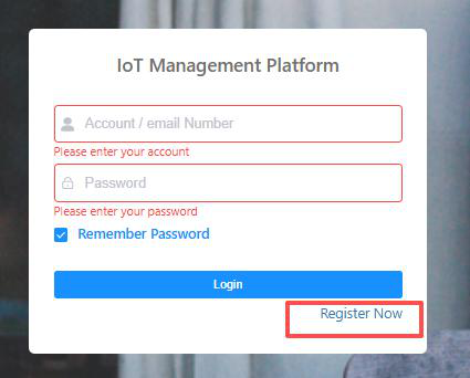
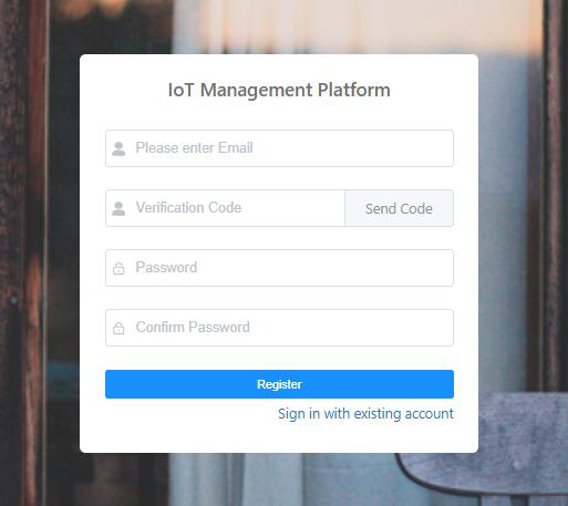
Go to http://adomodelcloud.com/ and click "Register Now". Follow the on-screen instructions to create an email account, then log in.
3.2.2 Channel Configuration - Device Addition
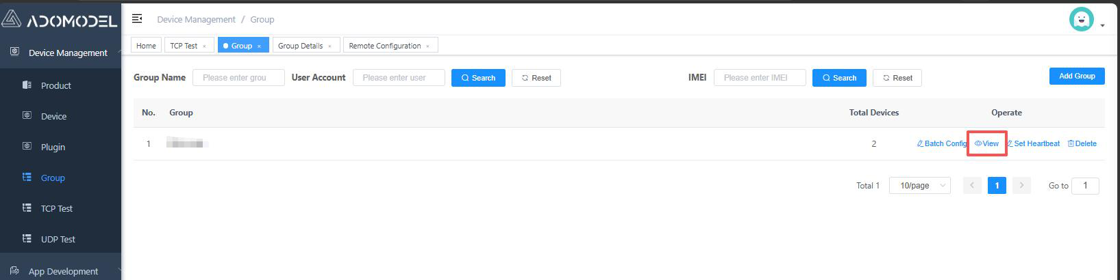
- Log in to the platform → Device Management → Group → Add Group.
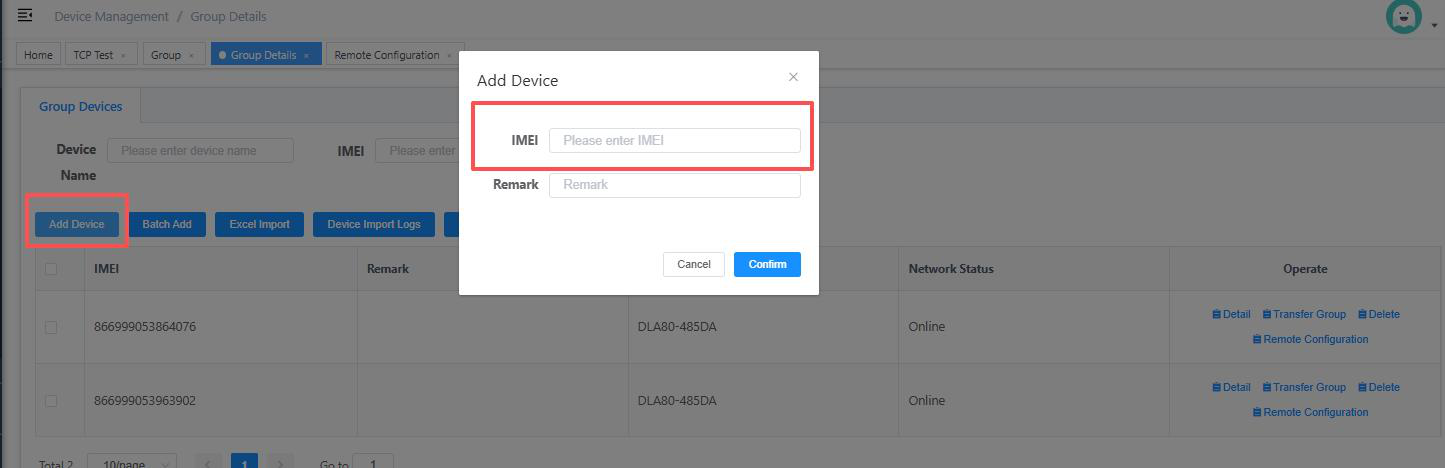
- Click View on the group → Add Device → enter the device IMEI (printed on the device label).
- Restart the device; once online it can be Remote Configured.
3.2.3 Device Configuration
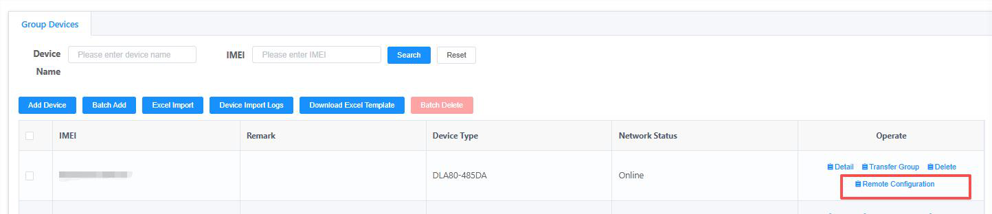
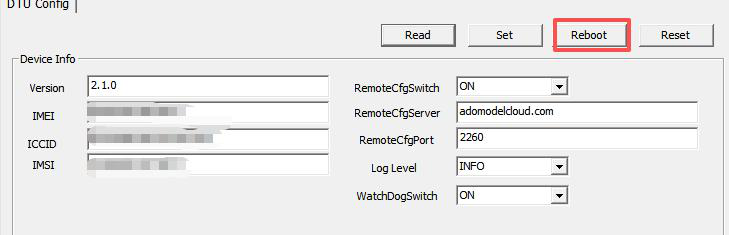
After the device comes online, click "Remote Configuration" in the device list to configure device parameters (serial port, Modbus, working mode, heartbeat, log level, reset, reboot).

4. Device Information
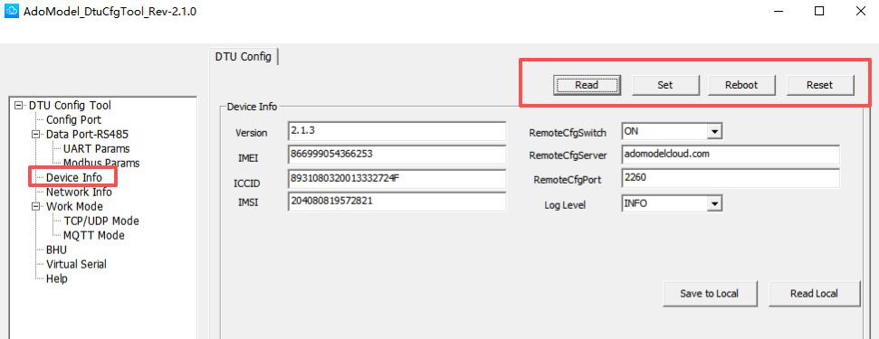
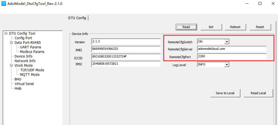
Click "Device Info" to read device info (version, IMEI, ICCID, IMSI), restart the device, restore settings, and configure the address of the remote management platform.
4.1 Management Platform Configuration
Enable RemoteCfgSwitch, enter the platform address and port, then restart the device for changes to take effect. Once disabled, the device cannot be remotely configured via the device management platform.
4.2 DCT Configuration Saving and Reading
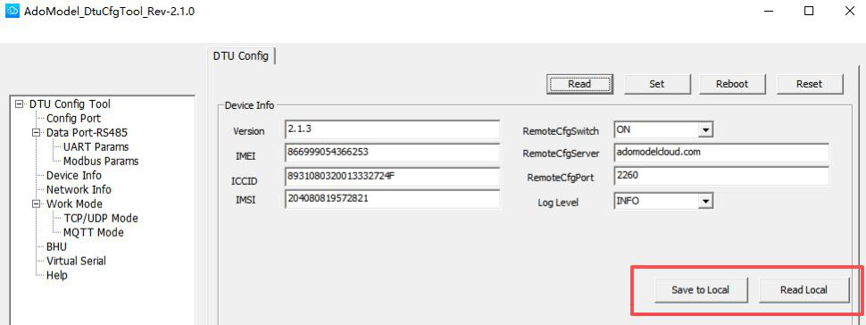
- Save to Local: saves the current page's configuration to the file
Ado_DtuConfig.cfgin the same folder as the DCT tool. - Load Local: loads the corresponding configuration for the current page from
Ado_DtuConfig.cfg.
5. NetWork Info
5.1 Dial-up Configuration
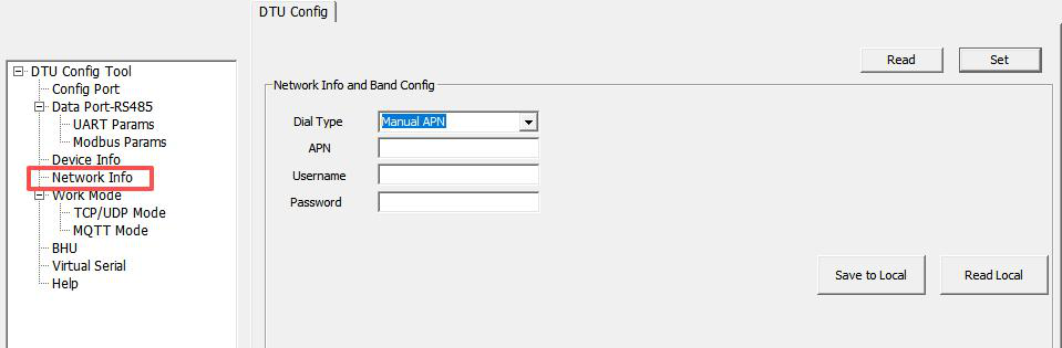
Dial type: Auto APN is set by default. Change to Manual APN if required.
For Manual APN, you'll need to enter the APN address, username, and password.
6. Work Mode
The working mode configures how the DTU connects to your business platform. Supported modes: TCP, UDP, MQTT, and AdoModel Cloud (managed platform).
6.1 Introduction to Configuration Parameters
Main settings: (1) working mode — selects the access method; (2) the corresponding parameters for the chosen platform.
6.1.1 Work Mode Configuration
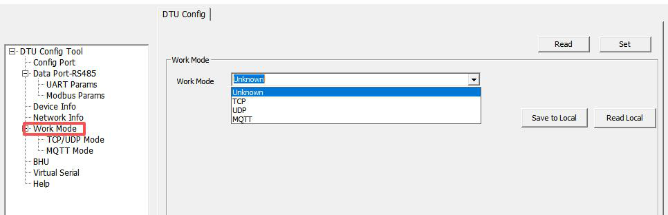
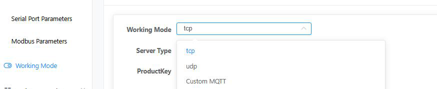
Open Work Mode in the local tool (or Remote Configuration on the platform), select the mode from the dropdown, click Set/Configure, click Read to view the current operating mode. Working-mode changes require a device restart.
6.2 Server Settings (Product Creation)
Before adding devices, create the corresponding product on the platform:
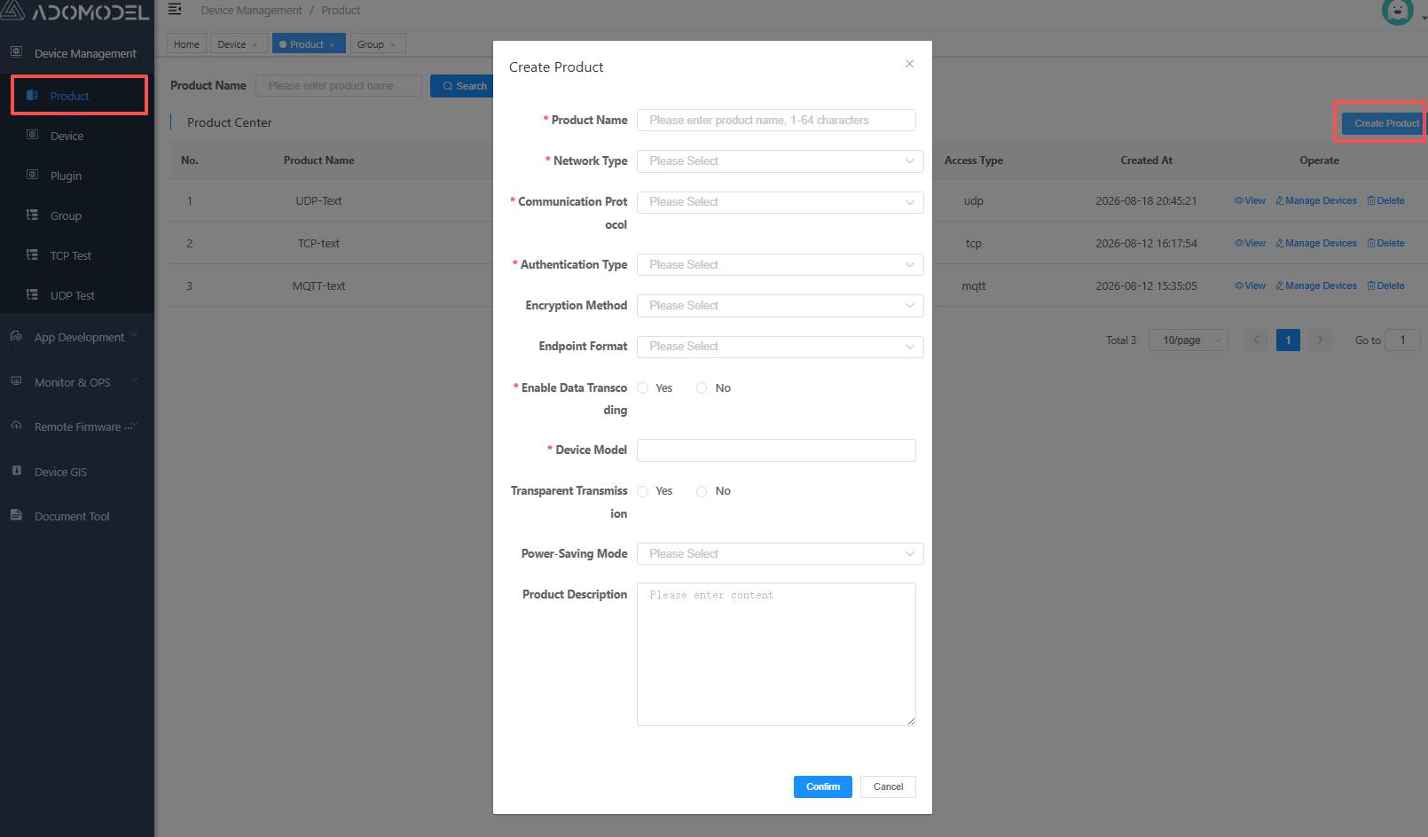
| Field | Description |
|---|---|
| Product Name | Customizable. |
| Network Type | NB-IoT / Mobile Cellular Network / Ethernet / Wi-Fi — select per compatibility. |
| Communication Protocol | LwM2M/MQTT/TCP/UDP/ LoRaWAN. Select the communication Protocol based on product compatibility and specific requirements. |
| Authentication Type | Currently IMEI only. |
| Encryption Method | Optional; multiple methods supported. |
| Endpoint Format | IMEI only |
| Enable Data Transcoding | Yes / No |
| Device Model | Customizable. |
| Transparent Transmission | Yes / No |
| Power Saving Mode | PSM / DRX / eDRX. |
| Product Description | Customizable. |

After creating the product, add the device with the corresponding IMEI. You can observe this by checking the device's label.
Alternatively, you can simply navigate to the product and add the corresponding device.
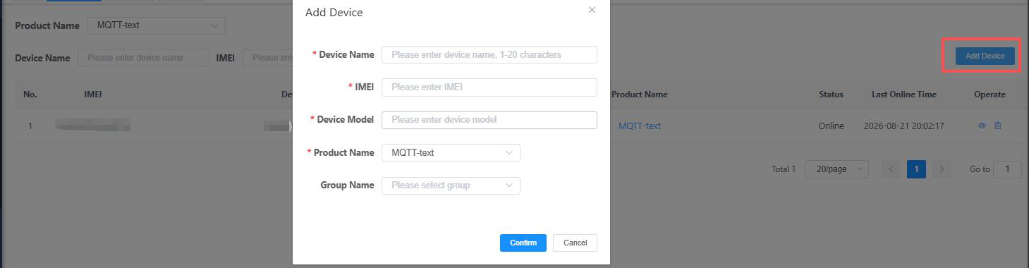
| Field | Description |
|---|---|
| Device Name | Customizable. |
| IMEI | Add the IMEI of the device |
| Device Model | Customizable. |
| Product Name | Select Based on Product |
| Group Name | Groups can be modified according to specific requirements. Further details are omitted here. |
6.3 TCP/UDP Mode
TCP/UDP operating mode requires selecting a service platform:
- If connecting to the AdoModel Cloud Management Platform, select the AdoModel Cloud Service Platform and enter the product name and product Secret.
- If connecting to your own platform, select the custom service platform and simply enter the server address and port number.
Taking the AdoModel Cloud Equipment Service Platform as an example, log in to the connection management platform at: http://adomodelcloud.com/.
Refer to the online documentation tool section, specifically the device access documentation chapter, to create TCP/UDP products and devices, and then you can proceed with the access test.

6.3.1 Local Tool Configuration
- Step 1: On the host computer, click on the TCP/UDP mode to configure TCP/UDP settings. Based on the connected platform, select the service platform type, enter the server address and port number, as well as the ProductKey and ProductSecret of the created product, then click Configure.
- Server address: You can directly enter the IP address or the website URL.
- Server Port: (0–65535), set according to the port of the server you need to.
- Set: Click Configure to complete the parameter configuration.
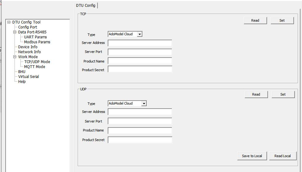
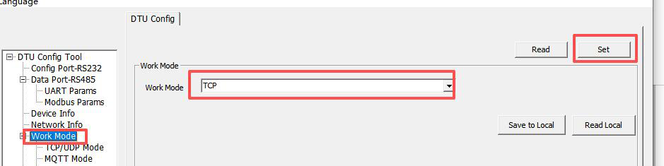

- Step 2: In the working mode, switch the Work Mode to TCP, click Configure, go to the device information section, and restart the device. After the restart is complete, check the Device Management Platform — Device Management — Devices to confirm that the device is now online.
6.3.2 Device Management Platform Configuration
Open Remote Configuration → Working Mode: select TCP or UDP; choose AdoModel Cloud (enter product name/key) or Custom (enter address and port); click Configure; restart the device.
6.4 MQTT Mode Configuration
Log in to http://adomodelcloud.com/, refer to the device access documentation to create an MQTT product and device, then configure:
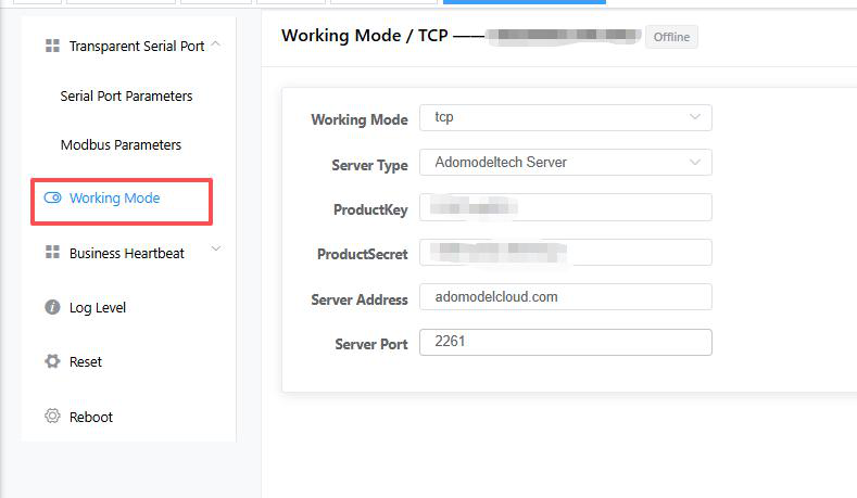
6.4.1 PC Configuration
- Step 1: On the PC configuration tool, click "MQTT Mode".
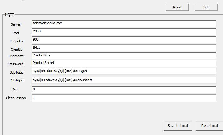
Fill in the connection parameters — Server, Port, Keepalive, QoS Level, Clean Session, ProductKey, ProductSecret, SubTopic, and PubTopic — copying each value from the MQTT product you created on the AdoModel Cloud platform (Products → Select the product → View). If you connect to your own MQTT broker, use the values provided by your broker administrator.
Click "Set".

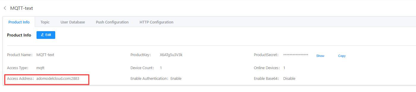
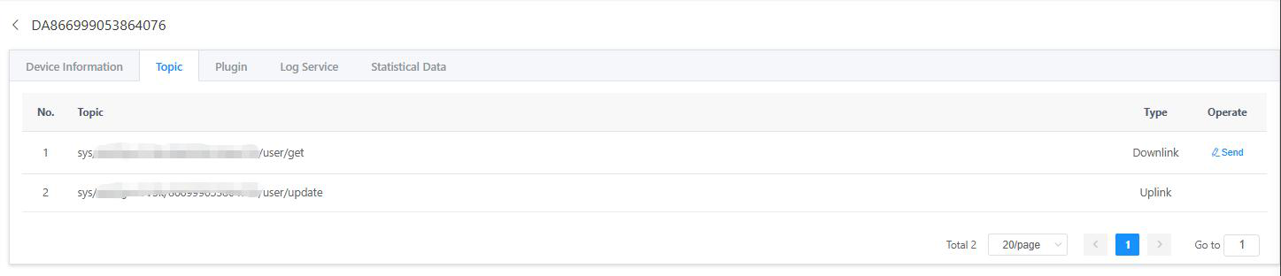
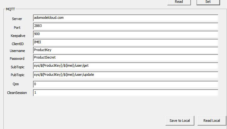

- Step 2: In the working mode, switch to the MQTT working mode, click Configure, and go to Device Management Platform → Device Management → Devices to check that the device is online.
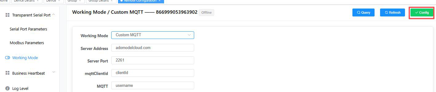
6.4.2 Device Management Platform Configuration
Open Remote Configuration → Working Mode → MQTT; fill broker address, port, keepalive, QoS level, Clean Session, product credentials and topics; click Configure; restart the device.
7. Pass-through Interface
7.1 Collection Function
Function: set the serial parameters between the DTU and external sensors or PLC. Parameters must match the slave device. Defaults: RS485, 9600 bps, 8 data bits, 1 stop bit, no parity.
7.1.1 RS232/RS485 Switching Function and Wiring Configuration
The pass-through interface can be switched between RS485 and RS232 in two ways: remotely on the device management platform, or locally via AT commands.
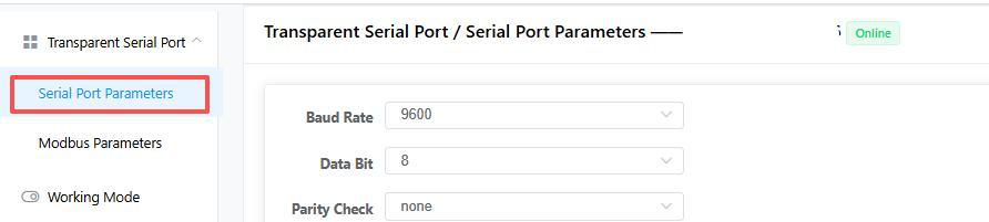
Method 1 — Switch via the platform (remote): On the device management platform, open Remote Configuration → Transparent Serial Port → Serial Port Parameters, select the interface, and click Configure, as shown in the figure below.
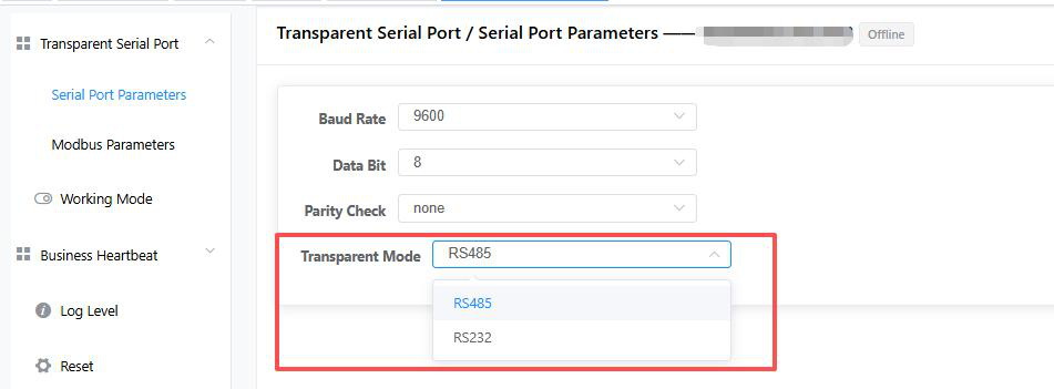
Method 2 — Switch via AT commands (local): Connect the DTU to your PC as described in Section 3.1 (RS232 terminal blocks + USB-to-RS232 cable, serial parameters 115200-8-N-1, then click "Open Port"), and send the commands below in the send window:
| Action | Command / Method | Note |
|---|---|---|
| Query current interface | AT+ADOCFG=get|transUart-mode | Reply 1 = RS485 (default), 2 = RS232. |
| Switch to RS485 | AT+ADOCFG=set|transUart-mode|1 | RS232 and USB ports still accept AT commands. |
| Switch to RS232 | AT+ADOCFG=set|transUart-mode|2 | WARNING: RS485 interface is disabled until switched back. |
Whichever method you use, confirm the currently active interface before wiring (see below). If the interface type was changed, restart the device for the change to take effect.
Wiring method: The DTU's transparent transmission interface connects to external devices via three screw-type terminals. Connect A+ to the external device's A+, and B- to the external device's B-. Be sure to pay attention to the configured transparent transmission interface when making the connection.
7.1.2 Local Host Computer Configuration
Serial port parameters: The default settings are 9600 bps, 8 data bits, No parity, 1 stop bit. When connecting to a device to collect data, the settings must match those of the external device. To modify the parameters according to the 485 peripheral device, click "Set" to save the settings. Click "Read" to view the current configuration parameters and verify whether the configuration has taken effect.
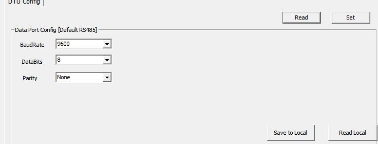
7.1.3 Management Platform Configuration
Click to pass through serial port, select the serial port parameters, and click Configure to complete the configuration of the pass-through serial port parameters.
7.2 Modbus Plugin
The RS485 interface features built-in Modbus polling and parameter parsing functions, enabling scheduled polling of bus sensor parameters and customized parsing of data collected from slave devices.
7.2.1 Polling Function
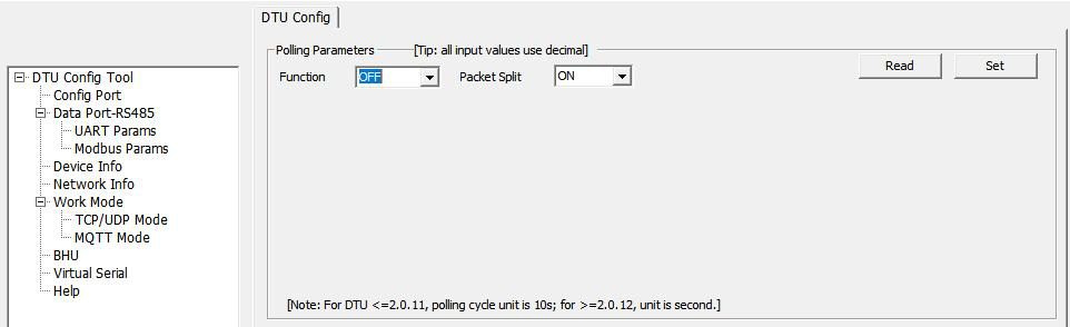
DTU supports polling of 6 Modbus channels. Before use, you need to first enable the function switch (which is disabled by default) and select the number of polling channels. Then, configure the parameters for each channel's Modbus slave device, including the slave address, function code, register address, data length, and polling cycle.
| Parameter | Description |
|---|---|
| Modbus Polling Switch | Toggle for the Modbus polling function. Disabled by default. |
| Packet Splitting CF | When enabled, this function splits downstream Modbus commands sent to the device. For example, a single downstream command 010300000001840A01030010000185CF will be split into two separate data packets at the transparent transmission port: 010300000001840A and 01030010000185CF |
| Channels | Supports up to 6 polling channels. |
| Slave Address | The Modbus slave device address. |
| Function Code | The Modbus slave device function code. |
| Register Address | The Modbus slave device register address. |
| Register Count | The length of the registers to be collected from the Modbus slave device. |
| Polling Cycle | The periodic polling interval for the Modbus slave device. Unit: 1 seconds. |
7.2.2 Parameter Parsing Function
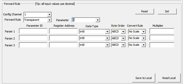
DTU supports parameter parsing functionality for the collected Modbus sensor data.
| Parameter | Description |
|---|---|
| Configure Channel | Select the corresponding Modbus polling channel. |
| Forwarding Rule | Transparent transmission is applied by default. Set to "Transparent" for channels that require data parsing. |
| Parameter | Specifies the number of sensor parameters to be parsed on the current channel. A single channel supports up to 6 parameters. |
| Parameter ID | Unique identifier for the parameter, which will be utilized in the subsequent Business Heartbeat function. |
| Register Address | The starting register address corresponding to the current parameter. |
| Data Type | The data type corresponding to the current parameter. The parser decodes the data based on the register address and length. |
| Byte Order | Byte order (endianness) conversion. Use ABCD, DCBA, BADC, and CDBA to represent different byte orders. |
| Conversion Rule | Configures the multiplier conversion. The default is "Raw Data". Other options include Multiplication and Division. |
| Multiplier | The calculation multiplier. Set to 1 for raw data. |
7.2.3 Modbus Slave Test Example
As shown in the figure below, this example reads data from 20 registers using a Slave Address of 1 and a Function code of 3. The following section will explain how to configure the system to obtain the corresponding data.
7.2.3.1 PC Configuration
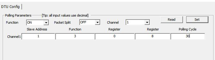
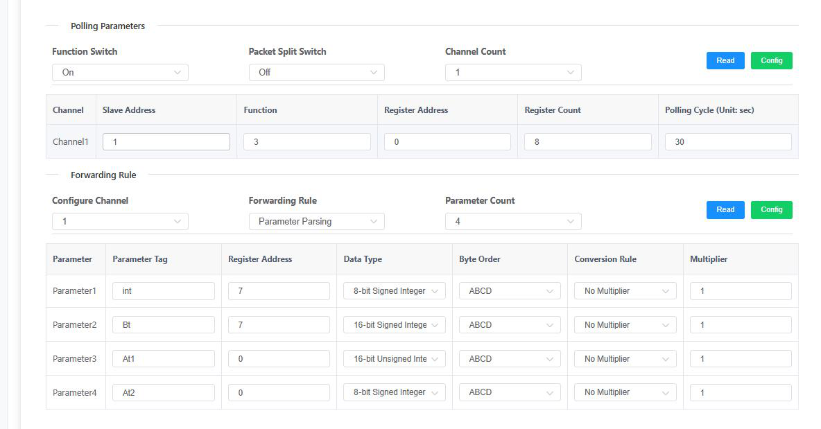
- Step 1: Enable the function switch. Set the total number of channel to 1 and the DTU polling channel to 1. Configure Slave Address 1 to collect data from register 0 to 8 of the slave device, with a Polling Cycle of 30 seconds.
- Step 2: Click the configuration button. Once the "Configuration Successful" prompt appears, the setup is complete, and the DTU will begin collecting data from the slave device.
- Step 3: Configure the data reporting format for the slave device.
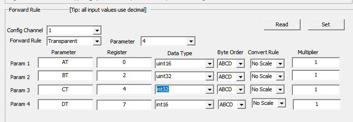
Channel 1: Enable Parameter Parsing and set the number of parameters to 4.
Parameters: Configure the Parameter as AT~DT, corresponding to the Register Addresses 0, 2, 4, and 7, respectively. The Data Type are uint16, uint32, int32, and int16. Set the Byte Order to default (no conversion), the Convert Rule to Raw Data, and the Multiplier to 1.
7.2.3.2 Device Management Platform Configuration
Select the Modbus Parameters and enter the correct data. Click Configure. A pop-up message indicating Configuration Successful will appear.
8. Business Heartbeat (BHU)
The business heartbeat feature supports the following scenario requirements:
- Registration and login message (actively reported once when connecting to the platform, used for authentication)
- Scheduled heartbeat messages (used to maintain the connection with the platform; typically short messages)
- Scheduled datagrams (used for periodically reporting business data, typically sensor device data)
8.1 Introduction to Configuration Parameters
Open the BHU tab in the local configuration tool to perform business heartbeat-related configurations.
| Parameter | Description |
|---|---|
| Packet | Select the packet type to be configured: Login Packet, Heartbeat Packet, Data Packet, Header Signature. |
| Function | OFF/ON, Disabled by default. |
| Packet | The packet format supports two configuration modes: HEX and String. |
| Cycle | Configure the periodic intervals for the heartbeat and business data packets. The Login Packet and Header Signature identifier do not require configuration. |
| Packet content | Packet content reported by the device to the platform. Detailed instructions will be provided in the following sections. |
8.1.1 HEX Message Configuration
HEX message configuration is relatively simple: Packet the HEX for the message format, then directly enter the corresponding HEX data in the message content Packet content.
a1 a2 b1 b2 38 …8.1.2 String Message Configuration
When configuring string messages, in addition to fixed data, users can also use common device wildcards and parameters configured in the preceding parameter parsing plugin to implement functions such as data collection and conversion. Wildcards are configured in the format of ${parameter}.
{"imei":"${IMEI}", " prama_time " : "${prama_time}"}Common Wildcards
| Wildcard | Description |
|---|---|
${IMEI} | device IMEI number |
${IMSI} | device IMSI number |
${ICCID} | device ICCID number |
${RTCTIME} | Current RTC time of the device |
${RSSI} | Current signal strength of the device |
8.2 Configuration Instance
8.2.1 PC Configuration
8.2.1.1 Login Packet Configuration
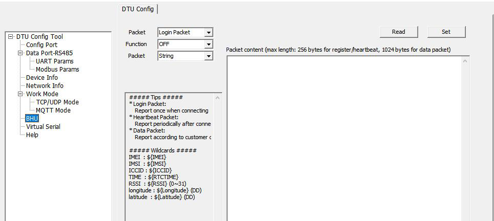
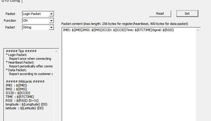
- Step 1: Click on Business Heartbeat, filter the message type to Login Packet, open the function, configure the message content, and use the wildcard
${IMEI}. You can directly see the IMEI number of the DTU device in the reported content. Use${parameter identifier}to extract the parameter and obtain its value. After configuring, click the pop-up window to confirm that the configuration was successful. - Step 2: Unplug and replug the power supply, wait for the device to power up again, and then check the device's reported logs for messages indicating that the login and registration packets have been successfully reported.

8.2.1.2 Heartbeat Packet Configuration
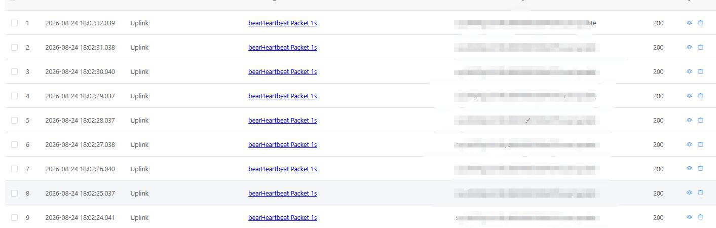
- Step 1: Set the message type to Heartbeat Packet, enable the feature, set the heartbeat packet upload frequency to 1 second (demo value — production recommendation ≥ 30 s to save traffic), and click Configure.
- Step 2: View the device log. The periodic heartbeat packet is uploaded every 1 second, and its content is as follows.
Interval rule:
| Configuration scenario | Result |
|---|---|
| Heartbeat interval ≥ data packet interval | Data packets report normally; heartbeat packets are NOT reported (data already keeps the link alive). |
| Heartbeat interval < data packet interval | Both heartbeat and data packets work normally. |
8.2.1.3 Data Packet Configuration
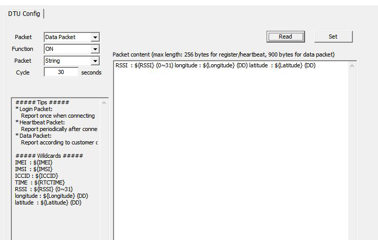
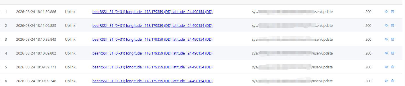
- Step 1: Set the message type to data packet, enable the feature, set the packet upload frequency to 30 seconds, and click Configure.
- Step 2: View the device log. The business data packet is uploaded every 30 seconds, and its content is as follows.
8.2.1.4 Header Signature
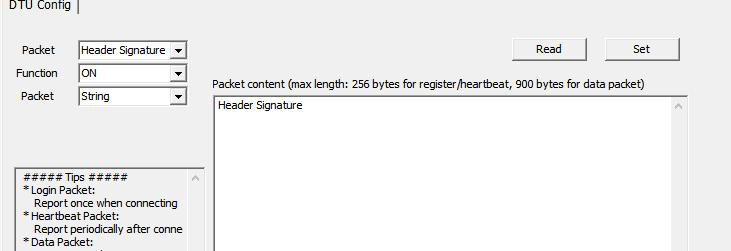
After the setting is applied, all upstream data from the device will have additional data appended to the packet header, including Modbus transmission, Heartbeat Packet, and Data Packet; however, Login Packet will not have any additional data added.
8.2.1.5 Message Format Packet Configuration
- Message formats are divided into string type and HEX type.
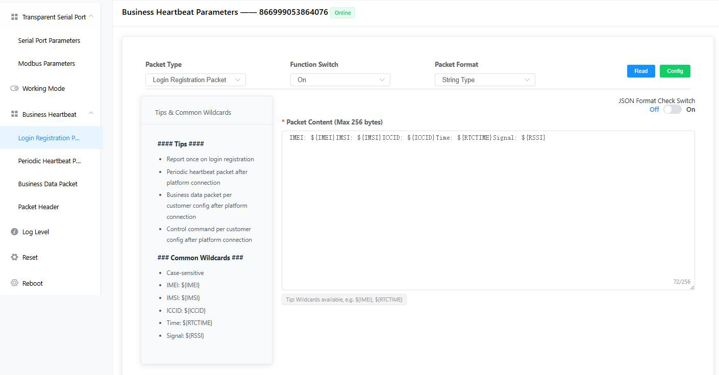
- For string types, directly input the data you wish to send. Note that wildcard text to be forwarded must be enclosed in
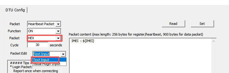
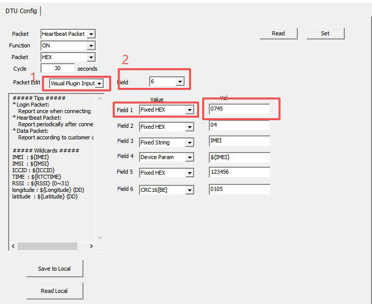
${wildcard name}, as shown in the figure below. - HEX type — The HEX type is further divided into two modes: text box input and visual plugin input. The editing mode will only appear after you select the HEX type, as shown in the figure below.
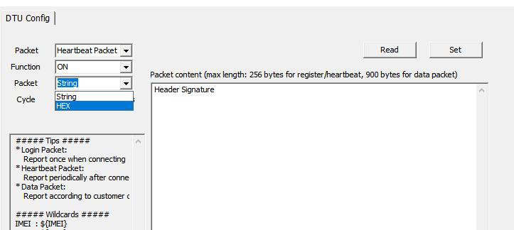
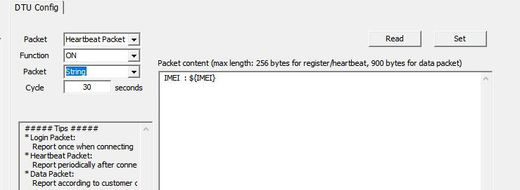
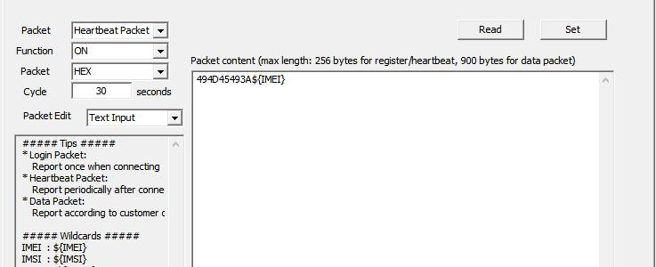
The Text Input format is as shown below — simply enter the HEX text directly. Wildcards can be set to any format.
Visual Plugin Input: Select characters by count (up to 10).
Values can be configured based on the value type: Fixed HEX data, Fixed string, Device parameters, CRC16[BE], CRC16[LE].
- For fixed data, simply enter the data in the corresponding format. Please note that string data must not exceed 16 bytes.
- Device parameters act as wildcards and should be configured accordingly.
- The CRC16 configuration is shown in the figure below. The CRC content spans from Field 1 to Field 8; therefore, enter
0108. If the content spans from Field 1 to Field 5, enter0105instead.
8.2.2 Device Management Platform Configuration
Open Remote Configuration → Business Heartbeat: select packet type, enable, set format/cycle/content (same wildcards apply), click Configure, restart the device, then verify in device logs.
9. Application Cases
9.1 MQTT Access Device Management Platform Case Study
- Step 1: Connect the Modbus slave device. Refer to the device's product manual to determine the baud rate, number of data bits, stop bits, parity, device address, function code, register address, data type, and data length of the transparent serial port for the device. Taking the MQTT transparent transmission mode connecting to a Modbus Slave as an example.
The sensor has a slave device address of 1 and a function code of 3. The valid register addresses range from 0 to 19, with data types including uint16, uint32, int32, and int16. The transparent serial port parameters are configured as follows: a baud rate of 9600, 8 data bits, 1 stop bit, and no parity.
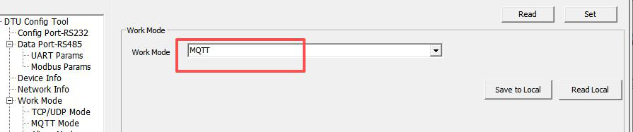
- Step 2: Configure the RS485 transparent transmission serial port according to the parameters from the device's transparent transmission port. After configuring the MQTT transparent transmission mode, restart the device to bring it online on the device platform.
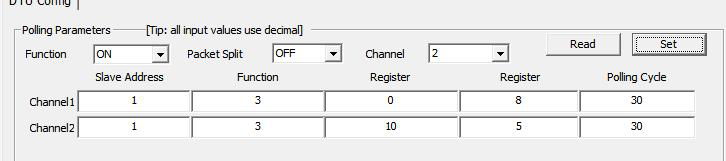
- Step 3: Enable the polling switch and set the number of channel to 2. Enter the slave address and function code.
Channel 1 collects 8 registers starting from slave device register address 0 with a polling cycle of 30 seconds.
Channel 2 collects 5 registers starting from slave device register address 10 with a polling cycle of 30 seconds.

- Step 4: Configure the parameters to be parsed.
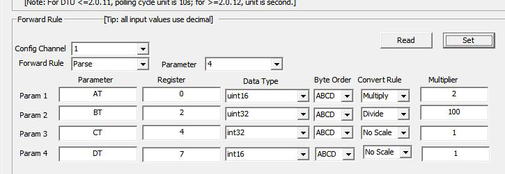
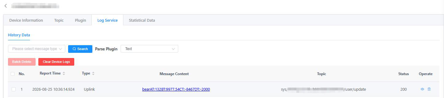
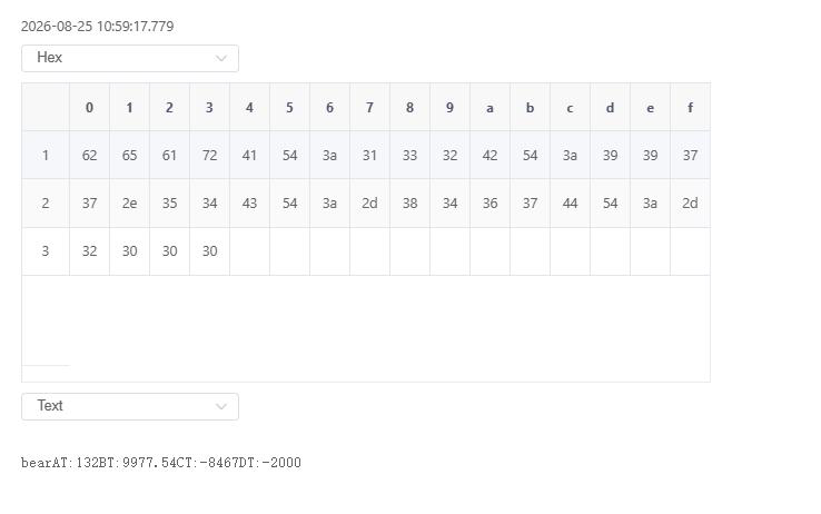
- Parameter 1: Assign AT to the 16-bit unsigned integer in register address 0. Set the byte order to default (no conversion), and the multiplier to 2.
- Parameter 2: Assign BT to the 32-bit unsigned integer in register address 2. Set the byte order to default (no conversion), and the multiplier to 100.
- Parameter 3: Assign CT to the 32-bit signed integer in register address 4. Set the byte order to default (no conversion), and the multiplier to 1.
- Parameter 4: Assign DT to the 16-bit signed integer in register address 7. Set the byte order to default (no conversion), and the multiplier to 1.
NoteWhen configured in parameter parsing mode, the collected values from the slave device can be converted into different message formats and reported to the platform via business heartbeats through parameter configuration. The parameter identification configuration rules are the same as those for programming parameter configuration.
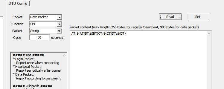
- Step 5: Click on BHU, select the business Data Packet and configure the reporting content and reporting time.
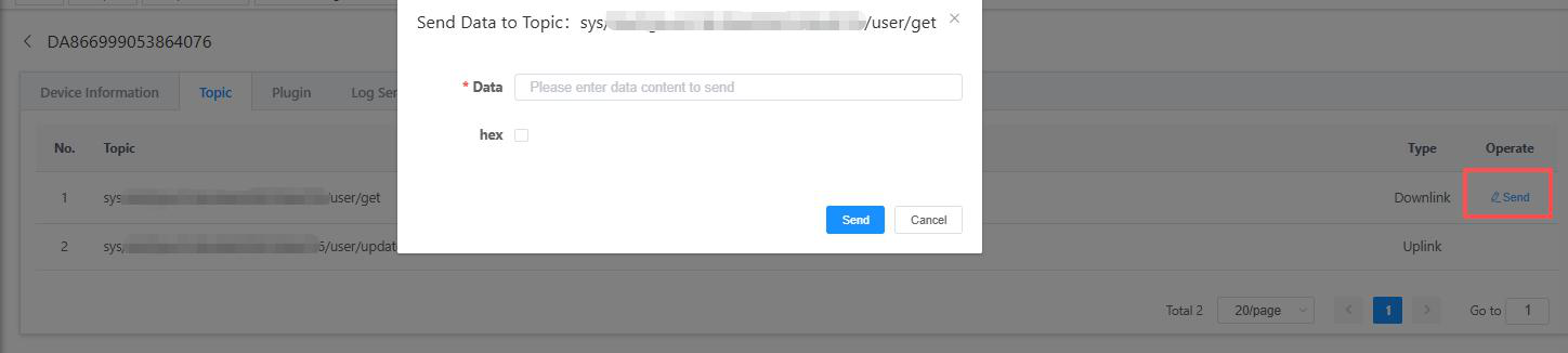
- Step 6: Log in to the Device Management Platform — Device Management — Device, click on the device details to view the device logs. You can see that business data packets are reported every 30 seconds. Click on the uplink data to send downlink data.
Data downlink:
10. FAQ
| Phenomenon | Possible Cause | Solution |
|---|---|---|
| POWER indicator off | No power connection or incorrect voltage | Check DC+/DC-, voltage range 9-25 V |
| WORK indicator always on | Device crash | Short-press reset button or power-cycle |
| NET indicator slow blinking | 4G network registration failed | Check SIM card, antenna and APN settings; verify carrier band compatibility |
| LINK indicator slow blinking | Failed to connect to platform | Check working mode, server address/port and product key |
| No change after configuration | Device not restarted | Restart after modifying working mode or key parameters |
| Device not displayed on platform | IMEI not added or device offline | Confirm correct IMEI; add after NET indicator stays steady on |
| No data from Modbus polling | Inconsistent serial parameters / wrong address / wiring error | Verify baud rate, device address and A/B wiring |
Appendix A: Common AT Commands
Device-specific commands use the AT+ADOCFG prefix. Standard LTE modem commands are also supported.
| Command | Description | Example reply |
|---|---|---|
AT+ADOCFG=GET|VERSION | Query firmware version (standard link test) | 2.0.15 |
AT+ADOCFG=GET|ALL | Query all configurations | multi-line dump |
AT+ADOCFG=get|transUart-mode | Query active data port: 1 = RS485, 2 = RS232 | 1 |
AT+ADOCFG=set|transUart-mode|1 | Switch pass-through port to RS485 | OK |
AT+ADOCFG=set|transUart-mode|2 | Switch pass-through port to RS232 (RS485 disabled) | OK |
AT | Basic handshake — quickest link sanity check | OK |
AT+CSQ | Signal strength, 0-31 (≥10 usable, ≥20 excellent). First stop for "NET LED blinks" | +CSQ: 24,0 |
AT+CPIN? | SIM PIN status — READY means the SIM is detected | +CPIN: READY |
AT+CGSN | Query module IMEI (matches the device label) | 86xxxxxxxxxxxxx |
AT+CGATT? | PS attach status — 1 = attached to the LTE network | +CGATT: 1 |
AT+CGDCONT=1,"IP","apn" | Set the APN (replace apn with your carrier's IoT APN) | OK |
Appendix B: Modbus Function Code Quick Reference
| Code | Function |
|---|---|
| 01 | Read Coils |
| 02 | Read Discrete Inputs |
| 03 | Read Holding Registers |
| 04 | Read Input Registers |
| 05 | Write Single Coil |
| 06 | Write Single Register |
Appendix C: Key Specifications
| Item | Specification |
|---|---|
| Model | DLA80-485DA |
| Cellular network | 4G LTE CAT4 (FDD-LTE) |
| LTE bands / SIM size | This device is authorized to transmit on LTE FDD bands B2 (1850–1910 MHz), B4 (1710–1755 MHz), B5 (824–849 MHz), B12 (699–716 MHz), B13 (777–787 MHz), B14 (788–798 MHz) and B17 (704–716 MHz). Before deployment, verify that your carrier operates on a supported band (see Section 5.1 for APN settings). |
| SIM card | Activated 4G data SIM; IoT/M2M data plan recommended |
| Power input | 12 V DC nominal (9-25 V), ≥ 1 A; use a certified (UL/ETL-listed) adapter |
| Data interfaces | RS485 (default) / RS232, software-switched |
| Config port default | 115200-8-N-1 |
| Data port default | 9600-8-N-1 |
| Modbus polling | Up to 6 channels; up to 6 parsed parameters per channel |
| Working modes | TCP / UDP / MQTT / AdoModel Cloud |
| LED indicators | POWER, WORK, NET, LINK |
| Reset button | Short press 1-5 s = reboot; press > 5 s = factory reset |
| Configuration file | Ado_DtuConfig.cfg (PC tool) |
For the full hardware specification (band list, RF characteristics, environmental limits), contact support@adomodel.com or visit http://adomodelcloud.com/.
Appendix D: FCC Regulatory Information
FCC ID: 2BWC6DLA80
This device contains an LTE transmitter authorized under FCC Part 22 (H), Part 24 (E), Part 27 and Part 90 rules. The device also complies with Part 15 of the FCC Rules as a Class B digital device, per the statements below.
- This device may not cause harmful interference, and
- this device must accept any interference received, including interference that may cause undesired operation.
Any Changes or modifications not expressly approved by the party responsible for compliance could void the user's authority to operate the equipment.
- Reorient or relocate the receiving antenna.
- Increase the separation between the equipment and receiver.
- Connect the equipment into an outlet on a circuit different from that to which the receiver is connected.
- Consult the dealer or an experienced radio/TV technician for help.